rei&asuka
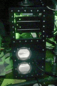 This project was very short lived. It was too unwieldy for it's intended purpose and was shortly replaced with a pair of laptops. Despite its brief lifetime I think this project taught me the most about simple metal fabrication and was certainly the most ambitious case mod project I've undertaken.
Looking back on the project there are a lot of things I would have changed, but it was fun to build - even with all the sleep deprivation with the end push to get it across the finish line.
sections
concept
cutting
electrical
paint
end
timeline
concept
The problem: A producer needs to frequently transport two PC's to put together music for live gigs. In addition, the computers are exposed to any number of conditions- heat, humidity, sweat, smoke, dust, vibration, impact, etc...
solution: Merge both machines into a single case for ease of transport. Add a forced air cooling system, air intake filters, a heavy duty steel chassis, plenty of weather stripping, a heavy dose of industrial style and you get ultrascience labs' Rei & Asuka.
cutting
A — Cutting
The Gateway P5-166 chassis. Formerly part of mdportal diablo; now it will house Asuka, Rei, and the cooling system for both computers.
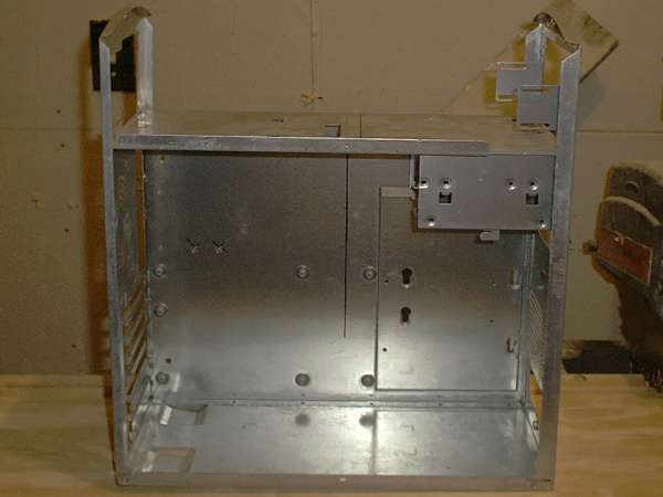
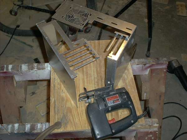
The Compaq Presario chassis. It will be cut down into a secondary motherboard tray to fit inside the Gateway chassis.

B — The motherboard tray
Some straightforward cutting is required to liberate the motherboard tray.

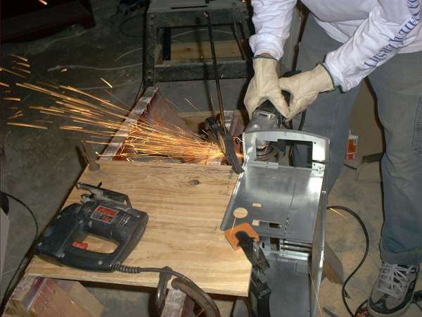
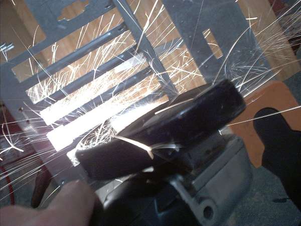
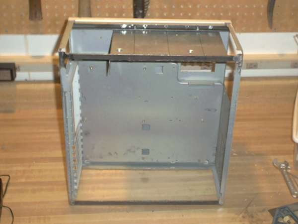
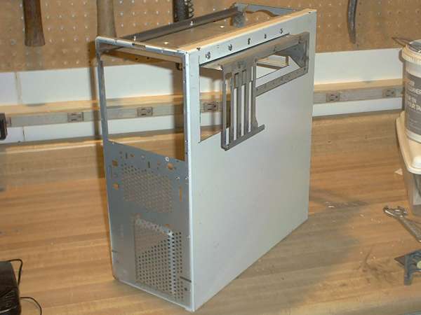
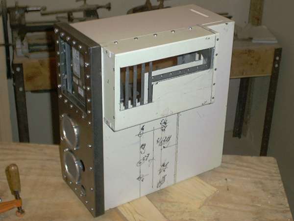
Braces made from steel angle iron and welded in place stiffen the main chassis and provide mounting points for the secondary motherboard tray. Mounted this way, the secondary tray extends out the side of the main chassis. Since this machine is designed for road use, a cover is needed to protect the extension.
C — The extension cover
The cover is fabricated from the case cover of another old chassis. Holes are being drilled to rivet corner braces on the cover so side panels can be added.
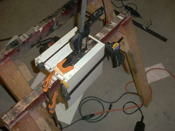
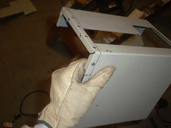
Test fitting the extension cover determines the location for bolt holes and brackets.
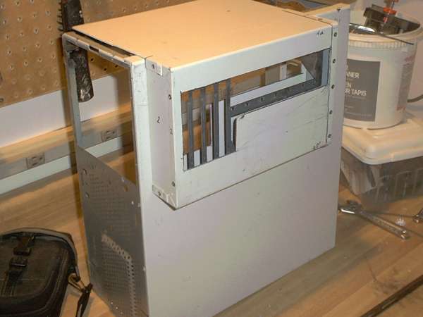

D — Mounting the decorative HDD
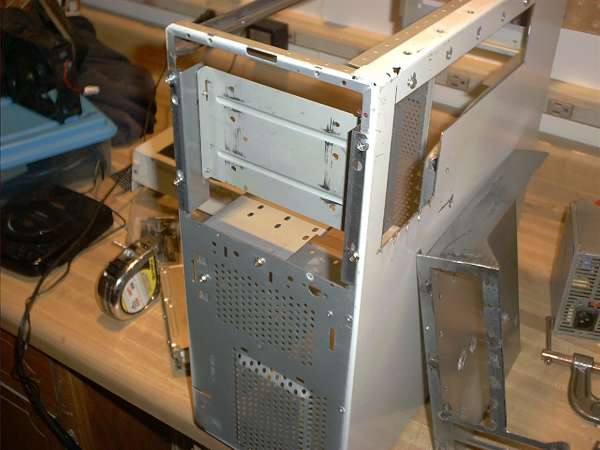
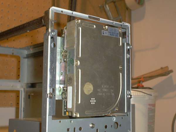
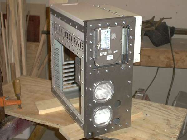
The secondary motherboard tray displaces the CD-ROM drives which have to be mounted externally. For effect, a decorative hard drive will be mounted in the front of the case. The bracket to hold the drive is fabricated from a drive bay adapter and a 3.5" drive mounting bracket.
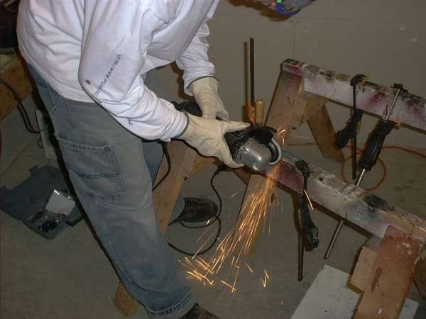

The bracket fits in the space that held the 5.25" drive bays. The hard drive shown is a Seagate 44MB drive.
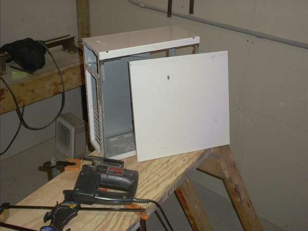
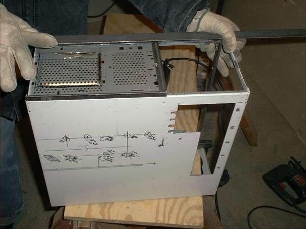
E — Separating the top, bottom, and side panels.
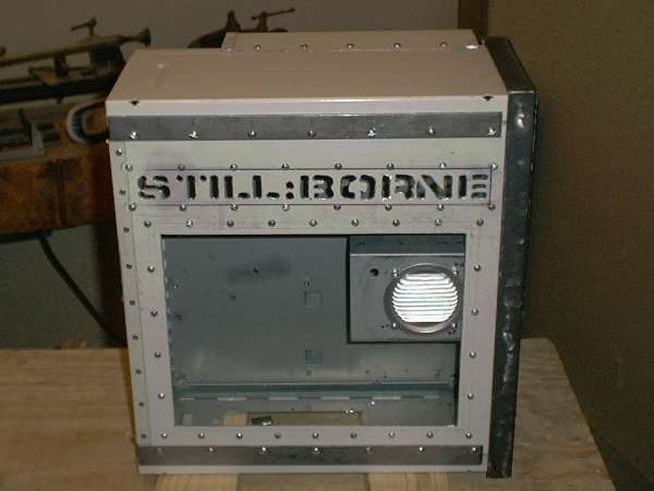
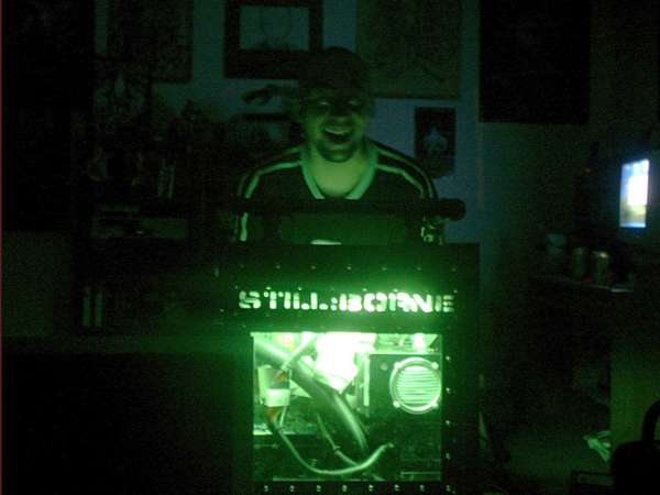
As this machine will serve as both instrument and visual effect, the side panel will have a lighted window and logo.
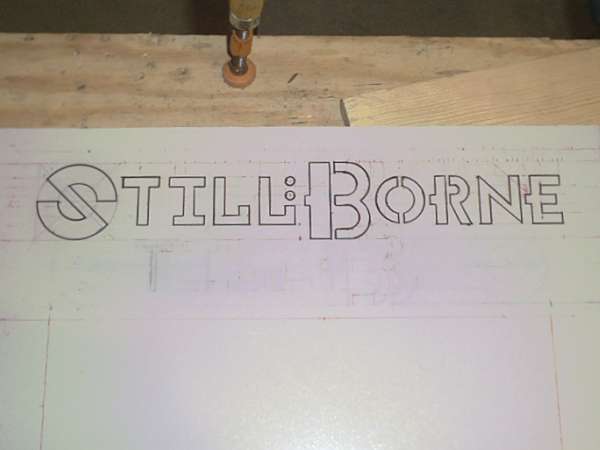
The original logo design didn't quite fit the theme of the case. A little searching produced a distressed stencil font that seemed more appropriate
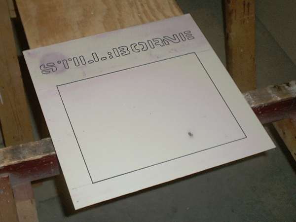
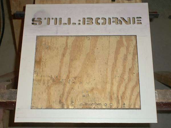
The steel bars will run along the top and bottom on the panel to seal the seams and provide strength.
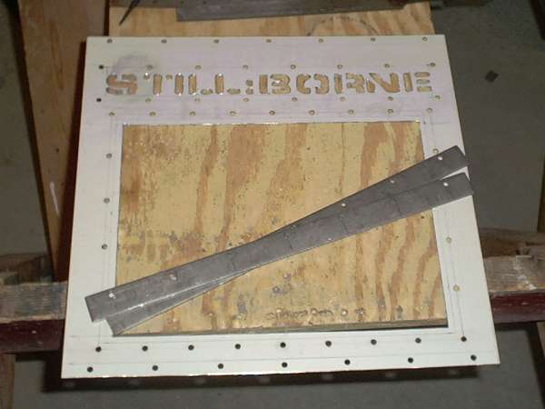
After all of this careful layout and cutting a major flaw was revealed- the layout was upside down. An embarrassing and costly mistake. Three solutions eventually developed- 1) remake the entire panel from another old gateway case, 2) cut out the still:borne logo and replace it with a steel patch with an appropriately positioned logo, or 3) swap the clips on the front edge with the flap on the rear. Because it would do the least damage and cost the least time, option 3 was chosen.
The repair process steps in order: 1) break spot welds holding down the front clip 2) flatten the flap on the back edge 3) trim the front edge of the panel and remove an extra fold of steel 4) cut the back edge flap from another case, trim it to length, add holes for rivets and screws 5) test fit
The next step will be fixing the clips onto the panel using some epoxy
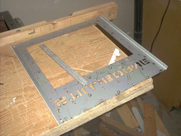
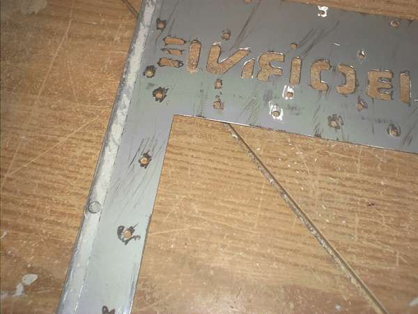
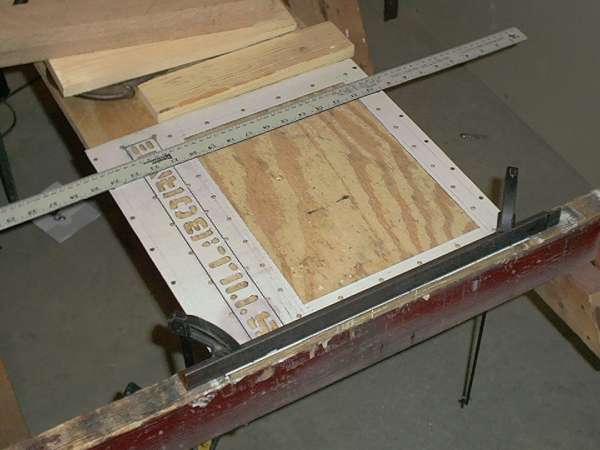
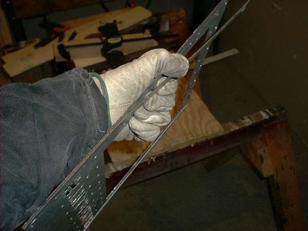

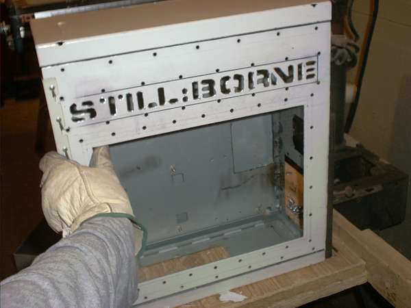
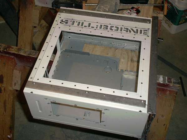
The epoxy didn't hold- so pop rivets are where it's at. With that, the repairs are complete.

F — Fabricating the air handling system
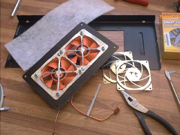
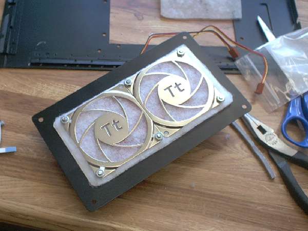
A typical air-cooled computer uses a number of fans to draw in and circulate air in the system. This cooling system uses the addition of ducts to direct cool air to the components of the system. Two Thermaltake Smart Fan II's will draw outside air through a filter and into a manifold where the flow is divided into the ducts. Three low profile fans will draw air out of the case and across the PSU's and HDD's.
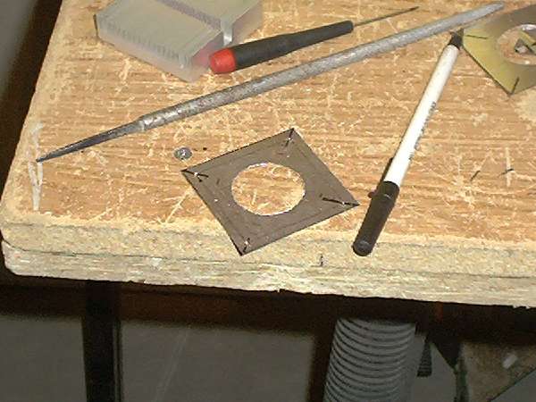
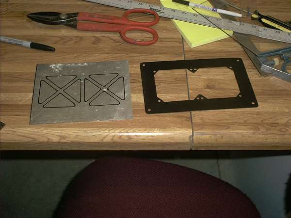
Here, the fan mounting plate is being laid out.

The manifold is fabricated from aluminum sheet metal. The manifold is attached to the fan mounting plate, and this assembly is bolted to the bottom panel of the chassis cover.
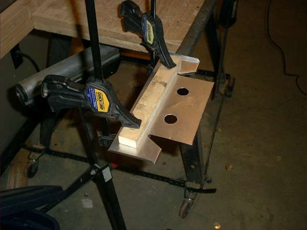


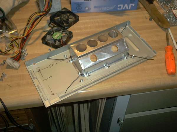
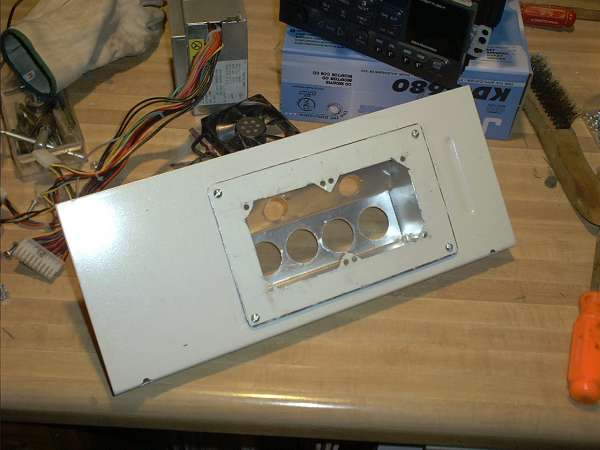
Sump pump hose is lightweight, flexible, and cheap. The black hoses are for the CPU's and video cards, and the smaller, white hoses are for the chipsets.
Plates cut from a bit of aluminum sheet will hold the ends of the hoses against the CPU heatsinks.
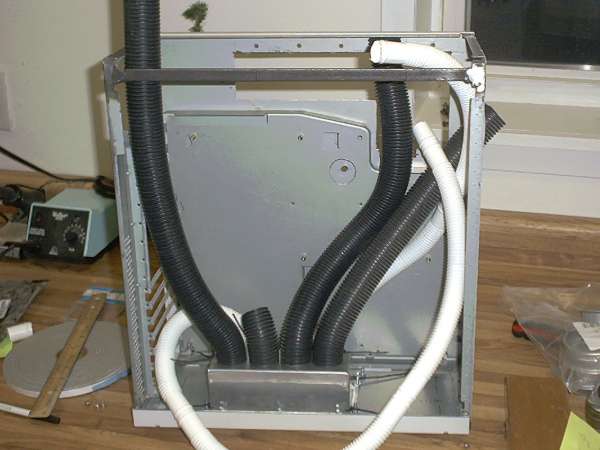
The air filter for the intake fans is held in place with a an aluminum bracket and a pair of fan grills. The bracket is custom and the grills came with the case fans.
G — Placing the power supplies
The design originally called for the power supplies to be externally mounted to provide room for the air intake manifold. Further progress revealed that some simple modifications to the power supplies and manifold design would allow the PSU's to fit inside the case.
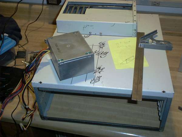
Both power supplies will be mounted in the front of the case, beneath the 3.5" drive bays. To allow for airflow and access to the power socket, a hole is cut in the front of the case.
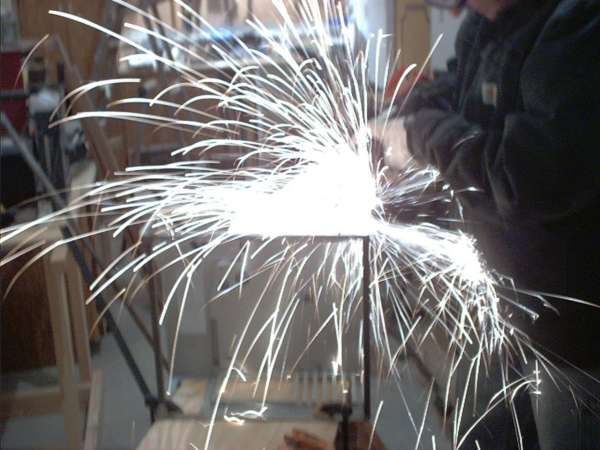

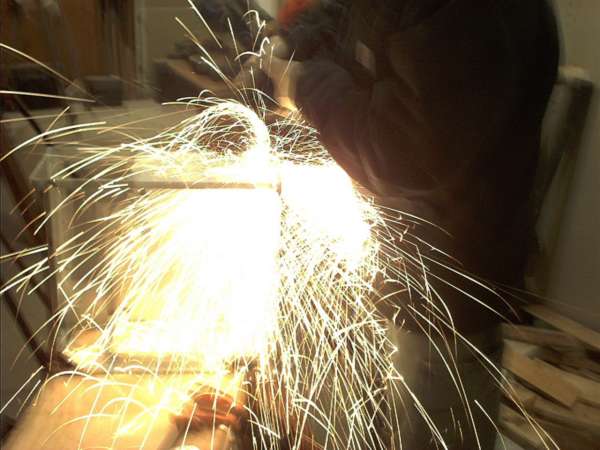
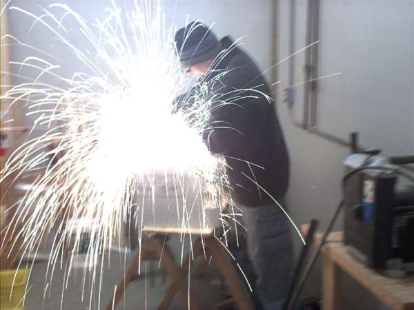
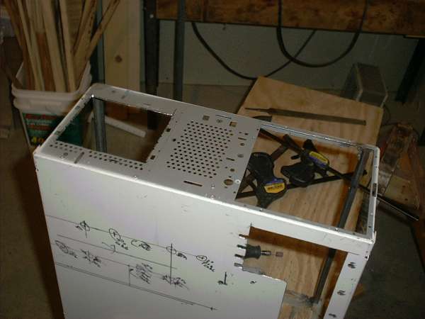
H — Fabricating the front panel
The original front plastic 'bezel' of the gateway case suffered from severe UV damage and really was inadequate for the needs of this case.
Hot air from the cooling system is exhausted past the power supplies and hard drives out the front of the case. Half inch angle iron will form a space for air movement.
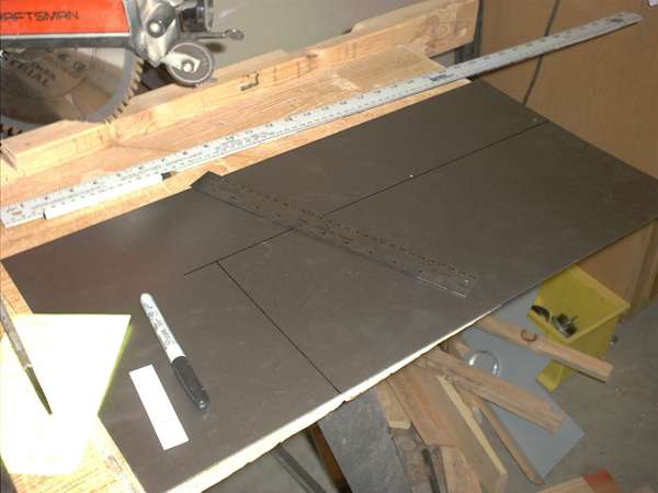
The front panel itself is constructed from steel sheet and one inch angle iron.
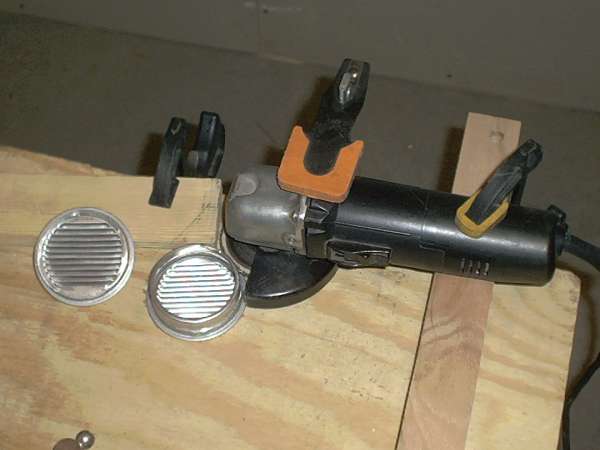
The pair of large holes is for a pair of decorative vents and, the smaller holes are for the power cords from the power supplies. The vents were excessively deep, but a simple grinder jig provided the means for trimming them to a uniform size.
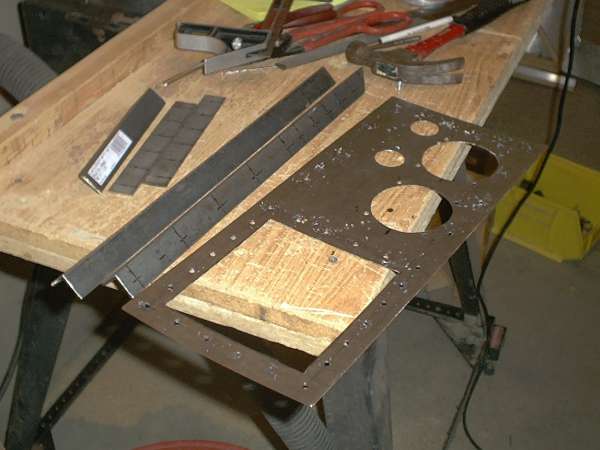

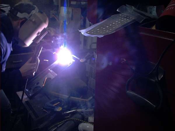
A little welding and grinding and the front cover is assembled. Some clean up grinding and final fitting remains, but it is complete enough for a preview.

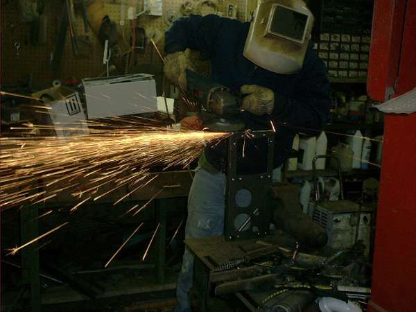
With the front cover assembled, the half inch angle iron used for spacing is welded in place. After that, a quick test fit. Only a little touch up work is required.
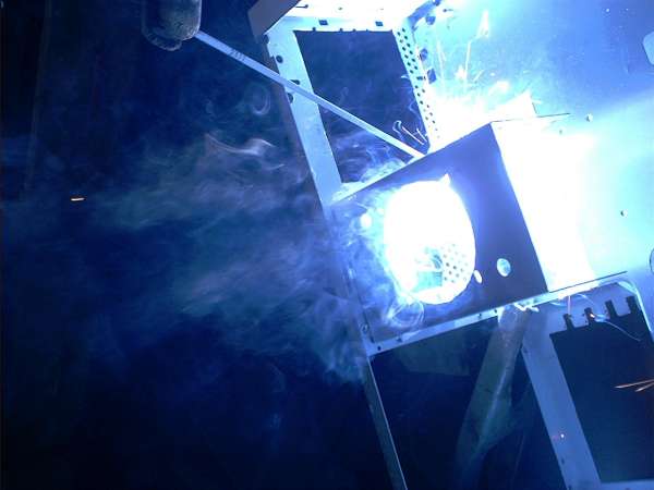
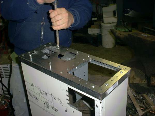
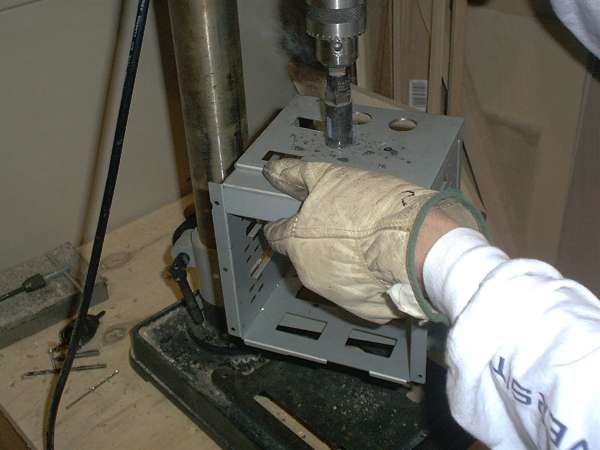
I — Break out drive bay and control box
A few people have asked, "Where are the CD-ROM drives supposed to go with all the power supplies and stuff?" Simple- outside the case. Don't worry, that was planned. Obviously the best way to hold drives is to use a computer chassis. Of course, why would anyone use an entire chassis to hold a few drives? Well the only part needed is the structure that supports the drives. An elegant solution is to simply take an existing chassis and chop it down into a mini-size.
The chassis of choice is from a Digital Starion 933. The goal- create a roughly quarter-size chopped version of the case.
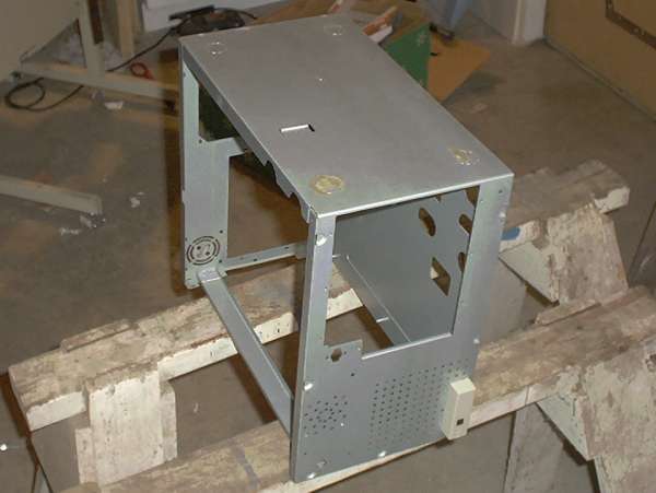
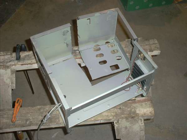
After chunking up the case into proper bits, the bits are assembled with a bit of welding. Image four shows the chassis next to the cover for a size comparison. The next trick is cutting the cover, plastic and all, to fit the new chassis.
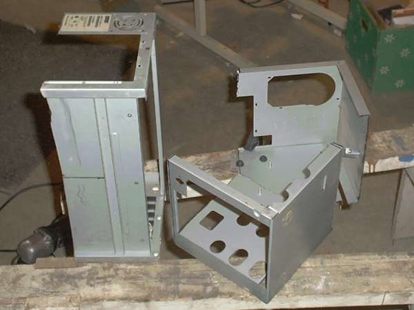
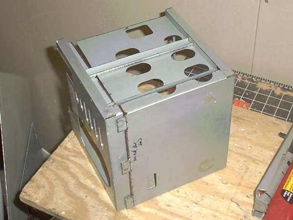
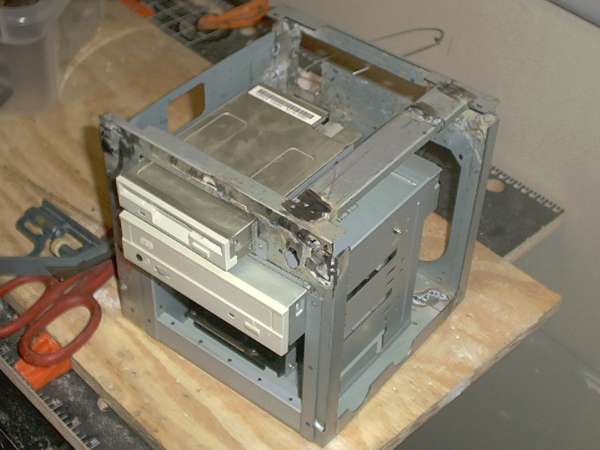
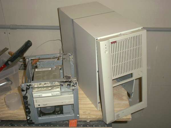
The cover for the bay is a chopped version of the existing case cover. Small clips salvaged from the original cover are attached to the mini version with rivets.
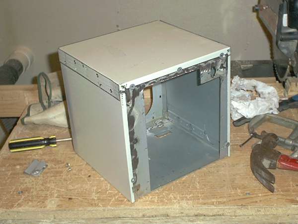
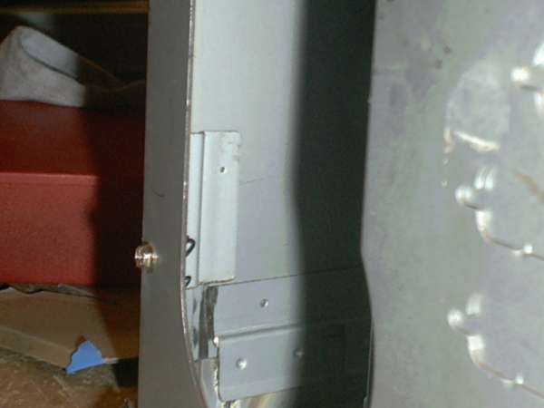
The plastic bezel was cut with a radial arm saw. Plumber's plastic pipe glue holds the top and bottom pieces together. The glue holds very well and any gaps between the pieces can be filled by using the plastic melting properties of the glue.

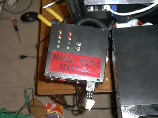
Power distribution and control is handled in a separate "control" box. The box holds a main power switch, the power and reset switches for both computers, HDD and power LED's, and power sockets for both power supplies and both monitors. The chassis just a gutted power supply with patches placed over the fan and vent holes.
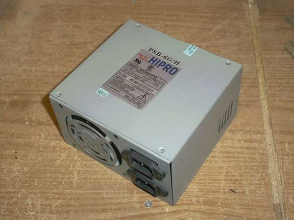
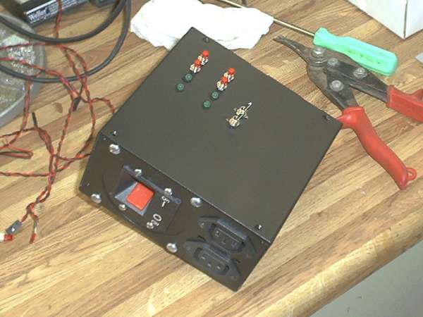
The bay and control boxes are attached to a frame described in the next section. The boxes are mounted to flanges that extend from the frame.
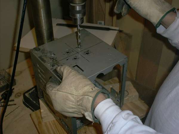
J — Black pipe frame
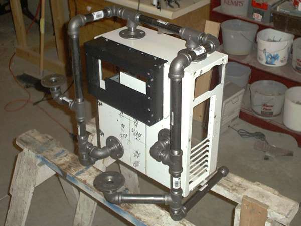
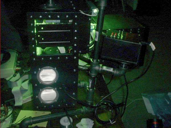
The break out drive bay and the control box are attached to the main case with a black pipe frame. The framework also supports the entire rig and serves as a carrying handle.
The trickiest part of building the frame is fitting all the pieces tightly while maintaining the proper spacing and positioning. Some trial and error fitting and careful measuring is required. Black pipe fittings are cheap and can be purchased at most hardware stores and home centers.

paint
A — Paint
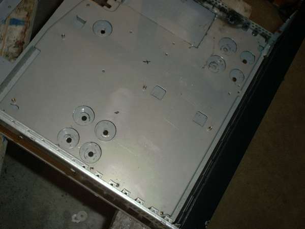
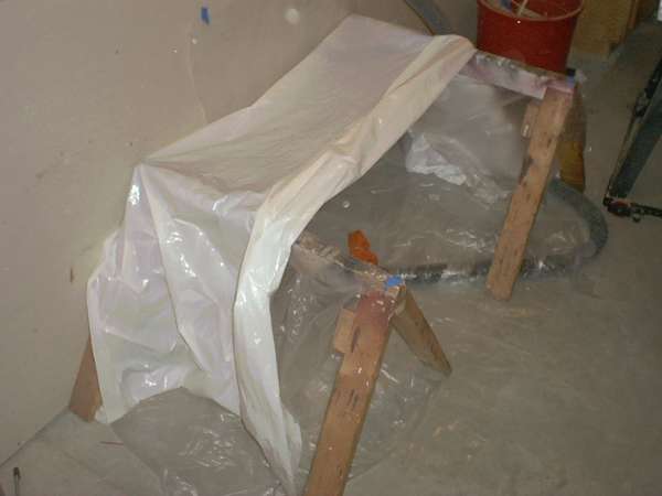
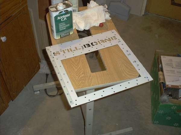
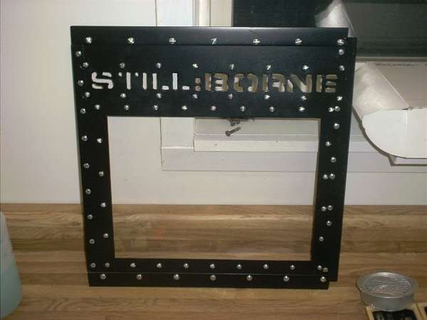
The paint process is the same as the ultrascience dragon. The only difference is the painting setup. A shop vac is added for removal of overspray dust and fumes. Just be sure to use a pre-filter, otherwise the main filter will get clogged with paint dust. A bit of polyester cloth from an old T-shirt works well. The polyester is elastic and breathes well.
Another helpful hint- try acetone for cleaning parts. It removes just about everything, even permanent marker. The only drawback is it's tendency to evaporate very quickly, so a fair amount is needed over repeated applications.
electrical
A — Lighting
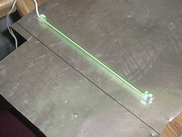
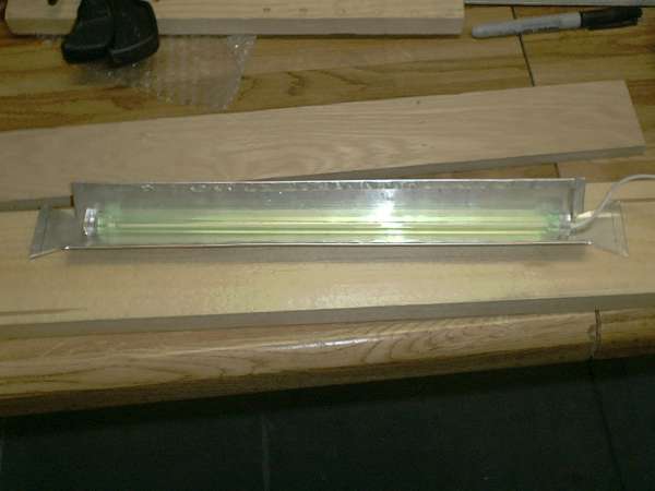
Cold cathode fluorescent and high intensity LED's handle the main lighting inside the case. The workspace is also supplemented with a cold cathode lamp mounted in a custom reflector. The high output LED's spotlight certain areas on the case; behind vents, backlighting structures, etc... In order to maximize the effect if the lights, the LED lamps are mounted in reflectors. The reflectors are cut from the bottom of Red Bull cans.

B — Fan control
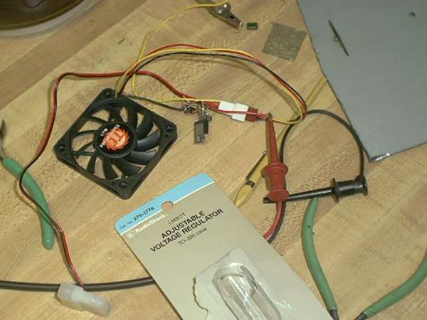
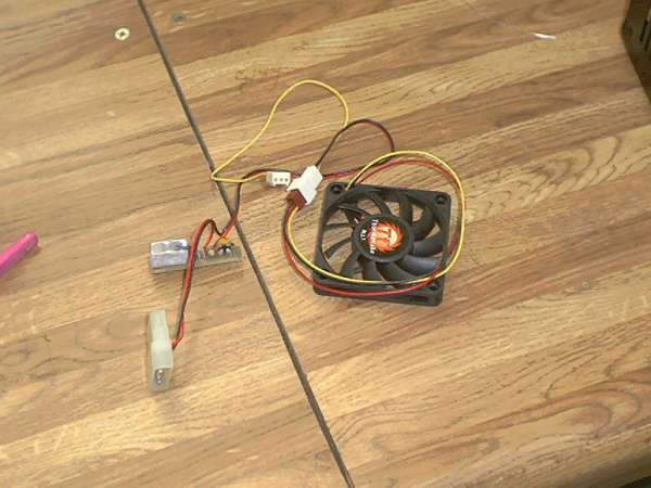
Two 60GB IBM HDD's will generate a fair amount of heat. A small fan mounted in the front of the case will draw air across the drives out of the case, helping to cool them. This fan is a compact, but rotates at a high RPM to achieve good air flow. A speed controller built around an adjustable voltage regulator will curb the noise level and hopefully extend the operating life of the fan.
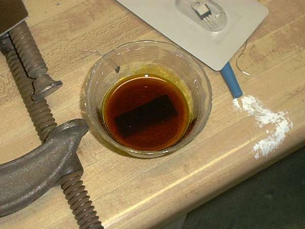
The controller circuit is very simple- a schematic is actually provided on the back of the voltage regulator package. The components are available at Radio Shack. A nice looking PCB for the circuit can be easily fabricated using a bit of copper-clad circuit board, some enchant solution, and a sheet of transfers.<
C —Power Supplies
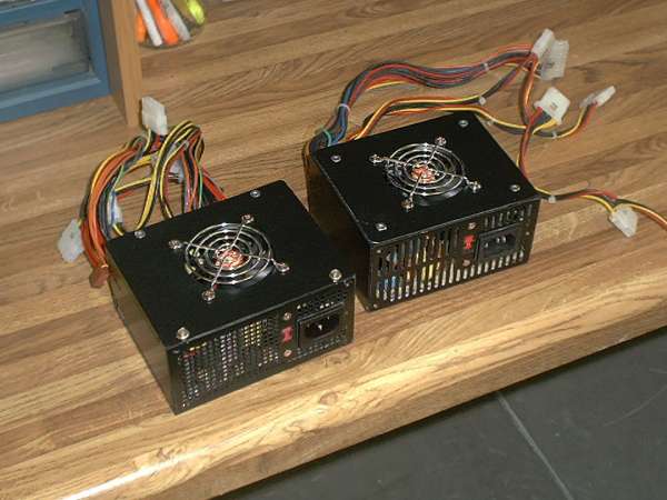
uATX power supplies are wonderfully compact, but fitting both in the case with space for ventilation required some streamlining.
WARNING: Note that disassembling or tampering with the power supply can be dangerous and at the very least voids the warranty. Attempt this at your own risk!
Replacing the original 80mm fans with compact 60mm fans would allow the fan to be flush mounted withthe top of the supply. The 60mm fans were pulled from Thermaltake A1151 CPU coolers (the heatsinks will be used for the CPU's.)

end
A — Preview
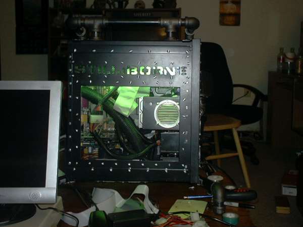
Rei & Asuka as of 12 / 20 / 02 11:41 AM.
B — Assembly fun
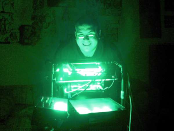
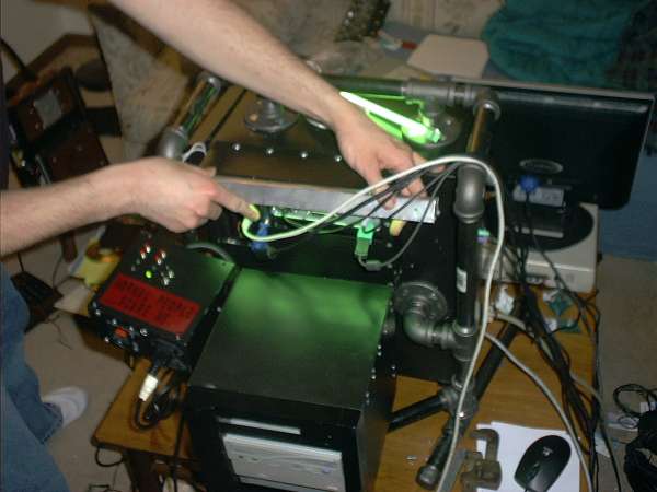
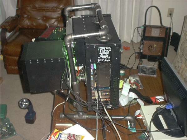
The paint, structural, and fab was finished the week of the 19th. On the 23rd and 24th, we pushed to get a chunk of the assembly done.
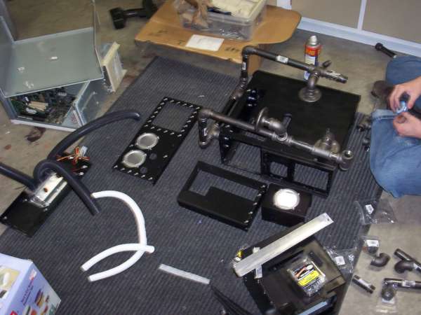

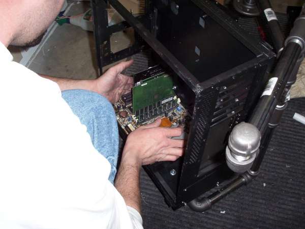
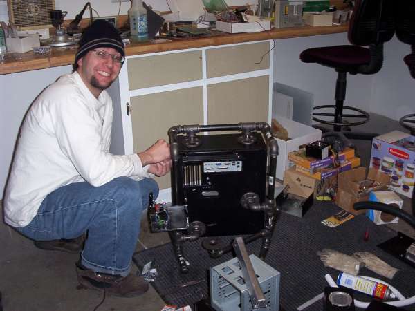

More assembly on the weekend of the 25th got Rei & Asuka to the point of being functional and cosmetically complete.



timeline
01/30/03 — 4 PM
It's been quite the project, but Rei and Asuka are assembled and working. A few finishing touches remain, but the cosmetic and structural aspects of the case are complete. After ultrascience moves to it's new location in Ames, all three of our current projects will be revisited. In the meantime, our focus will be on the web site on establishing our new facilities. Look for pictures from a live set when we revisit Rei & Asuka.
01/20/03 — 10 PM - 2 AM
New images are posted in teh cutting and electrical sections. Painting on the main chassis can begin tomorrow after yesterday's round of cutting. Later today's cutting projects will be the control box and maybe, just maybe, the HDD mod. Electrical work will continue on the fan speed controller and control box.
01/09/03 — 1:00 PM
Painting is under way, and three big fabrication projects remain- the break out drive bay, the control panel, and the windowed hard disk drive. The break out drive bay is nearly complete, and the control panel should be fairly simple. Check the cutting and paint sections for new pictures.
12/20/02 — 11:41 AM
Yesterday was a good day. Everything seemed to come together well. The cooling system test and power supply mod did not happen yesterday, but those will hopefully be projects for today. And yes, in progress pictures of Rei & Asuka are posted in the end product section.
12/19/02 — 12:30 AM
This has been an eventful day in the ultrascience labs production facility. A major cutting error forced the facility to a grinding halt. The window and 'still:borne' logo in the side panel were cut upside down. Emergency conferences resulted in a method for salvaging the work. Details are in the cutting section.
On 12/18, production was also halted due to equipment failure. The welding scheduled for 12/17 was postponed until this evening.
On a lighter note, the second power supply, the keyboards, mice, heatsinks, fans, and another 60GB IBM drive arrived just before midnight. Also delivered; a small stack of junk PC's for future work.
Today's goals: 1) set up and test the cooling system, 2) weld and mount the front panel, 3) modify the second power supply, 4) salvage the side panel, 5) in progress photo showing mostly assembled Rei & Asuka, 6) begin to plan the control panel and remote drive bay
12/08/02
Rei & Asuka have progressed nicely. The current completion date is Xmas 2002. New images have been posted.
10/15/02
Time to put my money where my mouth is. I tested an early prototype using CAD (cardboard aided design) technology. The system working remarkably well. It was able to keep a 550Mhz K6-2 from melting down. I've begun cutting on the chassis.