mdportal elite
introduction
 This case is a great example of turn-of-the-century modding techniques- it's all DIY. The availability of off-the-shelf case modding hardware and accessories was just taking off when we started the project- but we had no budget, so we had to get creative. All told, we paid about $50 US for a few components, cables, paint, nuts, bolts, and jigsaw blades. Everything else we had on hand in our junk piles.
The name of the case, 'mdportal elite', came from a website called "Mike's Diablo Portal" or "mdportal" that my brother and I put together to share resources and information related to Diablo, Diablo II, and StarCraft - the Blizzard games we were playing at the time. We tucked our casemod project work into a corner of that site. The below text is pulled directly from a backup of the mdportal website dated from September 2002. It's pretty terrible, but I've left it intact except for some light editing for spelling and clarity. I've added footnotes to add clarifying comments where needed. The photos are also pulled from my backups and are of the low quality typical of the time. Enjoy?
concept
The mdportal elite case was conceived in late October 2001. mdportal crew member Mike needed to test some old Fujitsu SCSI hard drives that had fallen into his lap. I pulled out my ancient Acer Inc. (now Aopen) VI15G motherboard with an ST Micro 486DX2 80 (yes, the same folks that produce the Kyro), and my ancient IBM SCSI controller card and went to work. The HDD's worked great so I put together a little machine in an old 386 case so we could play some of our favorite old games- System Shock, Civ 1, WarCraft2, SimCity, Privateer, etc. As is turns out, the school had received this old server/raid array case that had a few of these Fujitsu's inside with little else. It was donated to the school, but they had no use for it and no storage space to waste, so my brother volunteered to take it off their hands. The tech dept. head agreed and mdportal became the proud owner of a monstrous, old, and all steel (even the front bezel) chassis of some flavor.
With the case was another 500MB Fujitsu HDD, for a total of 3, and removable drive enclosures. An old 3com Etherlink/MC 32 card was lying forlorn at the bottom, and four Cofan 8012H12 80mm fans were mounted; two in the front and another pair in the rear panel. Two 300W AT power supplies topped it all off. As soon as I laid my eyes on that steel monster I had only one thought in mind- case mod!
When we began the mod, our design was focused towards an industrial look- dark grays, lots of metal, welds and grinding marks, and plenty of wires and cables. Soon after the project was underway the design took a 180 and shifted toward a more streamlined and clean look. Definitely a little retro, but clean lines and a lighter blue/gray color scheme were chosen in the end; mdportal elite was born.
mdportal elite is by no means a state-of-the-art machine. Since this project was our first case mod, we decided to make it as low cost as possible. We had that 486 DX2 80 "old school" gaming machine and that became the basis of the project. So first things first, a parts list:
components
- Acer VI15G motherboard w/ 128KB cache and 32MB RAM
- VLB I/O card
- VLB 2MB Cirrus Logic video card
- ISA ESS 1868 sound card
- ISA Future Domain 8bit SCSI controller card
- ST Micro 486 DX2 80Mhz CPU
- Four 8020H12 Cofan 80mm, 27.6 CFM, 27dB fans
- One Papst 3312 90mm, 47.1 CFM, 37dB fan
- Three Fujitsu M2684 500MB SCSI HDD's
- Two Compaq 1.05 GB SCSI HDD's
- One 16x Toshiba CD-ROM
- One 3.5" Floppy and one 5.25" Floppy, both from an old 386
- Four Storcase DE100i-S (SCSI 8-Bit I/O) hot swap bays
- Two 300W power supplies, one Morex and one US Power
- One 7 stub SCSI cable, one single device IDE cable, one floppy cable, one power cable
hardware
- One IBM 286 desktop case
- One string of 35 blue x-mas lights
- Two cans of spray paint, one winter gray, the other smoke gray and one can of metal primer
- One 3ft. stick of 1in. wide by 1/8" thick aluminum
- Some 8x32 and 10x32 machine screws and nuts
- Some 1/4" by 3/4" and 1/4" by 2" bolts and nuts
- One chunk of 1/16" thick clear acrylic from an old picture frame
- Several chunks of split loom tubing from a junk motorcycle wiring harness 1/4", 1/2" and 3/4" dia.
- A bunch of little zip ties, or ny-ties- whatever you want to call them
- A length of lamp cord
tools used
- random orbital disc sander
- cordless drill
- angle grinder
- jigsaw
- Dremel
- screwdrivers
- BFH (big f'in hammer)
- 7/16" wrenches
- pliers
- wire stripper
- soldering iron
- clamps, lots of clamps
- gas ax (oxyacetylene torch)
- welder
- multi-meter
fabrication
To begin our project, we needed to find a way to mount our motherboard in our server case. We decided to take the chassis of an old IBM 286, cut it down, and mount it in the big chassis. With our "industrial" theme in mind, we would simply weld the tray into the bigger case. Be sure to wear your safety gear, and do torch work outside, or under a heavy duty fume extractor.
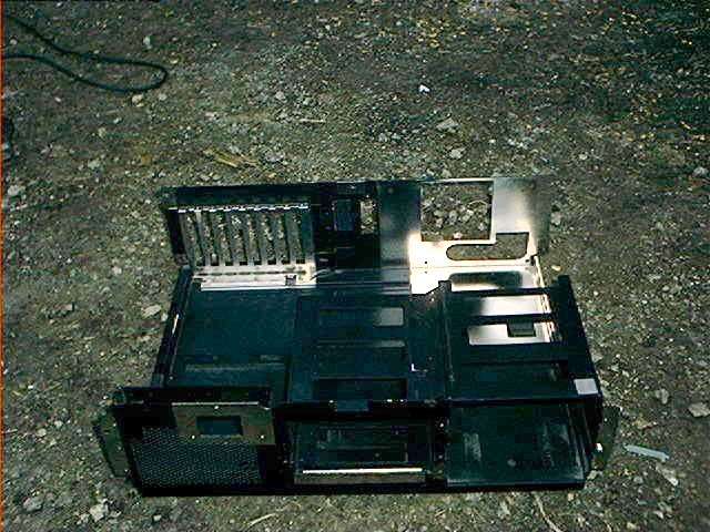 286 case before cutting
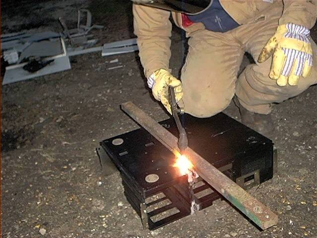 Doug torches away, using a draw bar as a straightedge
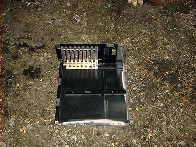 No more drive bays
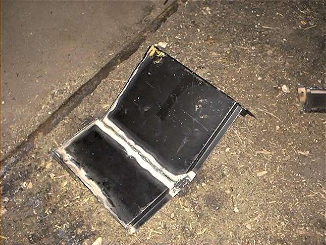 The last torch cut
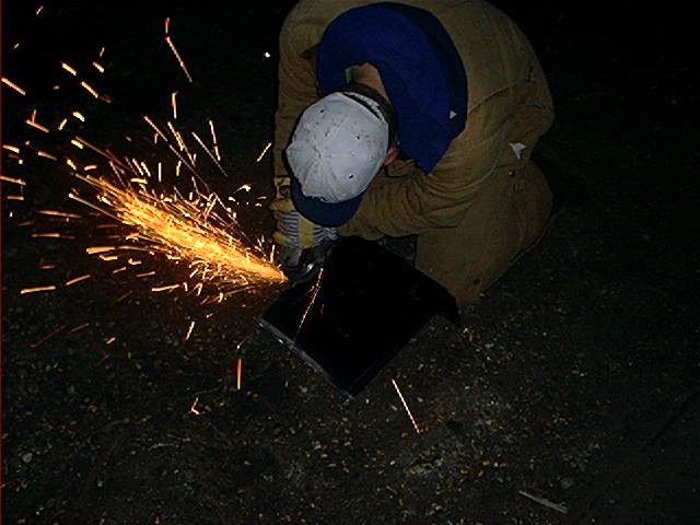 Doug grinds off the torched edges
After the next pictures were taken, we decided against the industrial look and ground off the welds. This way, we could mount the tray in place using bolts and spacer blocks so it would "float" and then we could make a decorative access panel on the side of the case to get to the bolts.
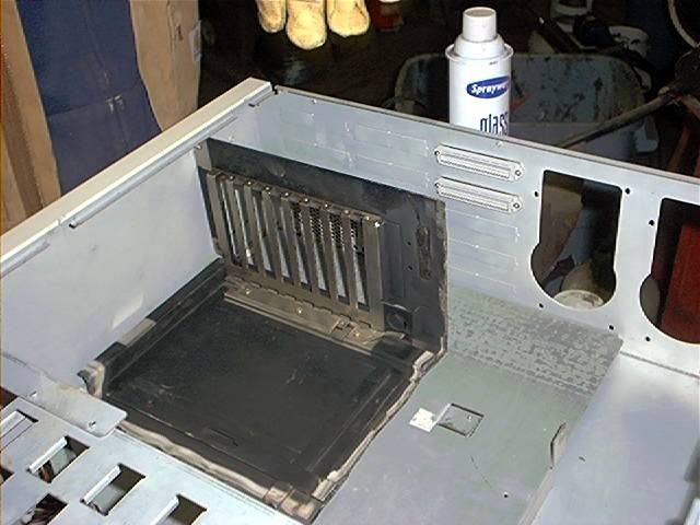 Aligning the 286 chassis for install.
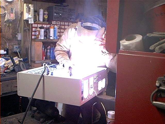 Welding the chassis in place.
Next, I added the blowhole in the top of the case to ventilate the HDD's. I cut the hole using a jigsaw and drill, then smoothed the edges with the Demel. Safety glasses are highly recommended when using the jigsaw.
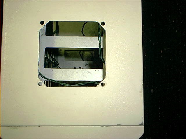 The blowhole, sized for the 90mm Pabst fan.
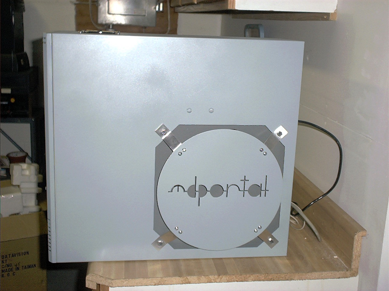
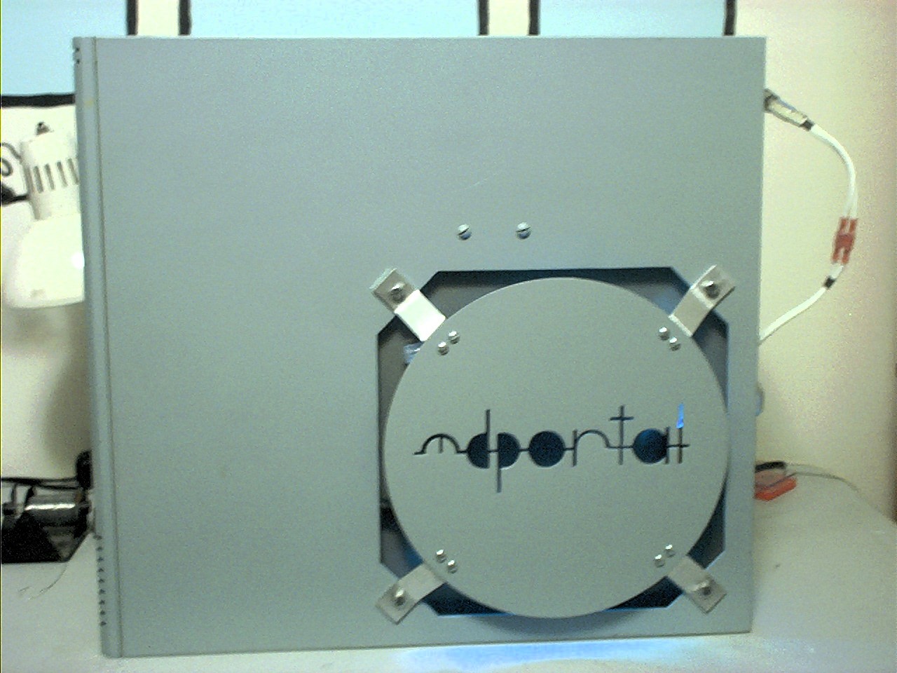
After the blowhole, I cut the access panel on the side of the case. Using the shape of the blowhole as inspiration, we decided to cut the hole in a similar octagon shape, then the panel itself would be a circle attached using aluminum brackets. In this way, the shape of the access panel mimics the shape of the blowhole and the chrome fan guard and the brackets bump the panel out for wrench clearance. I cut the mdportal logo first, then the circle, finally, the octagon hole. The case is double walled (check out the alignment pic above) leaving a 3/4" ish gap between the side panel and this inner sheet of metal. I used a sawed off jig saw blade just short of this gap size to do the cutting. I cut off the blade using an angle grinder.
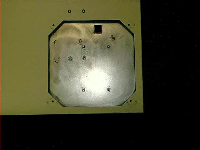 The octagon
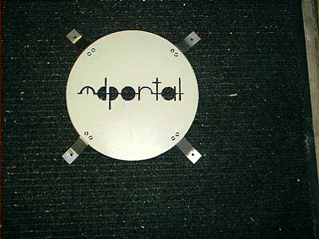 Access panel with logo cut and hand made aluminum brackets. Dig that brushed aluminum finish. Too bad it doesn't show up well. And yes, I cut that logo with a jigsaw- it was a pain.
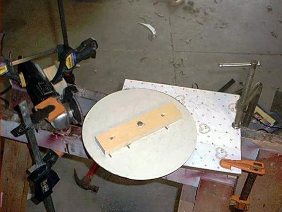 Here is a shot of the jig I set up to grind off the edges of the panel to make it perfectly circular. The panel is clamped between two blocks of wood using screws. That assembly spins on a bolt that runs through a chunk of plywood. Just be sure to center everything CAREFULLY. Wear safety gear when using your grinder.
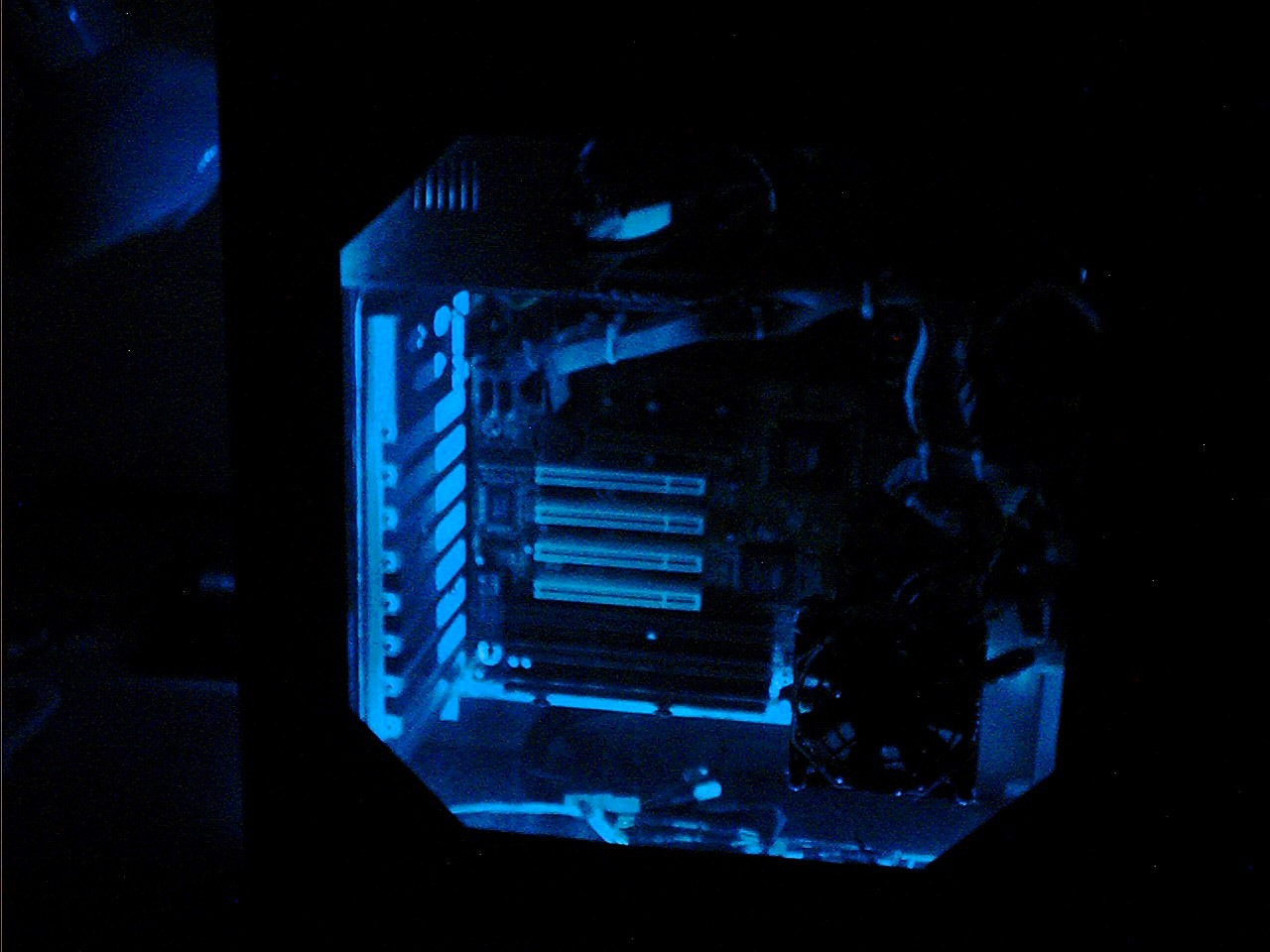
Next, the removable side panel window. This was an easy job. Jigsaw the window, drill the bolt holes, then layout, score, and snap off the acrylic to size. Just be sure to make the acrylic panel bigger than the hole. Notice that the shape of the window still carries that octagon shape thing.
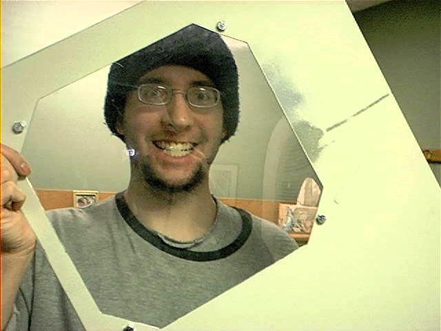 Here's me and the side panel window. You can see splotches of test paint... OOoooOOO preview. Another tip: I attached the window to the side panel using 1/4" bolts, but I drilled the holes in the plastic at 5/16". Even if the holes in the plastic weren't perfectly aligned with the side panel, now there is a little fudge factor and I can tighten the window in place without fear of cracking or warping it. Be sure to use washers between the plastic window and the nut to prevent plastic cracking.
If you look at the second picture in this group, you can see a pair of wing nuts. As it turns out, that fixed in place platform had a loose edge that rattled against the side of the case. A quick scrounge turned up a couple of big washers and some machine bolts. Why wing nuts? Cause they look cool.
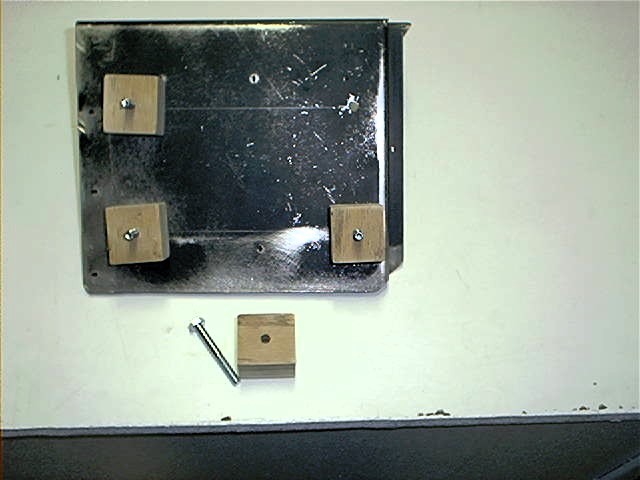 Motherboard tray with the welds ground off and the edges further trimmed. We used blocks made of plywood to elevate the tray. This aligns the ports with the cable pass thrus, and we can hide some wiring under it.
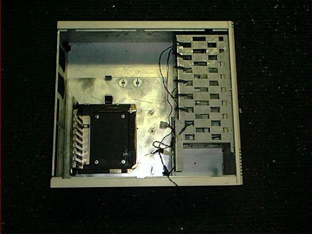 The tray bolted in place. You can see the rectangular holes cut in the back of the case for cable pass thrus. Yes, those are blue Xmas lights. More on those later...
painting
Our paint job is pretty straightforward. Two solid colors, winter gray and smoke gray. The first on the exterior surfaces, the latter on the interior and for the drive fronts and the drive bay cover plates. We used cans of spray paint, of course.
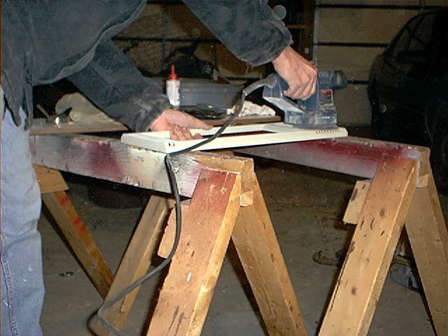 Step One: Sanding
Here's me sanding the front bezel. Sanding takes off the big chunks and smooths out the pebbly texture from the old finish. I also sanded down any grinding marks and sharp corners.
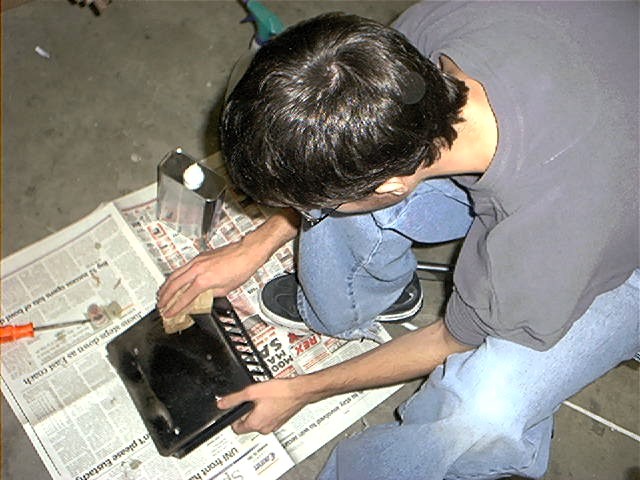 Step Two: Paint Prep
Here's Mike cleaning up sanding residue, oil, and dirt. First we used some automotive 409 for the dirt, oil, and dust. Then a bit of paint thinner to take off any cleaner residue.
electrical
Now we get to play with Xmas lights and stuff. Why Xmas lights? A) Cheap. I had a couple strings lying about. B) they run off of AC power so I could run them in parallel to the power supply. This allowed me to use one power supply and one switch to run the whole system. If you decide to use Xmas lights, remember that the bulbs run on a specific voltage in conjunction with the number of bulbs on the string- i.e. 120V divided by 35 lights on my string equals 3.4ish volts per bulb so I need to use 3.5 volt bulbs. I modified the string of lights by adding and removing lengths of wire between the bulbs to get the proper spacing. Split loom tubing holds the bulbs in place
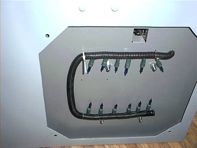 Here's a shot of the lights behind our logo. I drilled pairs of holes for zip ties after test fitting the bulb strings.
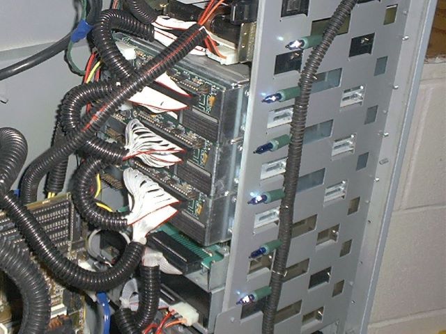 Lights along the side of the window. Bits of wire hold things in place.
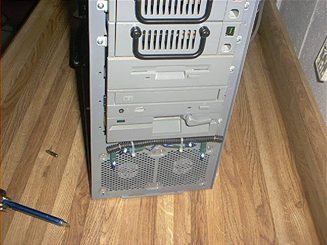 Light mounted behind the bezel. There are also lights behind the motherboard tray and under the blowhole fan.
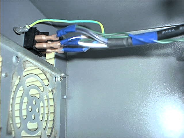 The lights are wired in parallel to the power supply so both run from a single switch. Remember to use electrical tape or heat shrink tubing to cover all of your solder joints.
I consider data cables part of the electrical system as well so I include it here. This section basically shows you how to round cables. If you know how to do that, then just ignore this bit.
To round your data cables, you'll need a razor blade, maybe a sharp tip marker, and some zip ties. First, divide your cable into equal sections. I used strips of 5 for my 50 pin SCSI cable, strips of 8 for the 40 pin IDE cable, and 4 strips of 7 and one strip of 6 for the floppy cable.
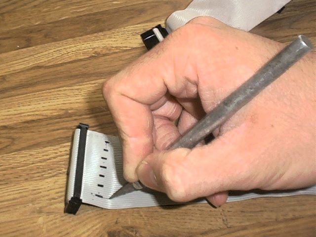 Use the X-acto knife to carefully cut a short slice in the insulation between each strip. Then, gently continue the split by tearing it with your fingers. If you accidentally expose a bit of the metal wire, just cover it with a bit of electrical tape. As long as you don't sever any of the wires, the cable should be fine.
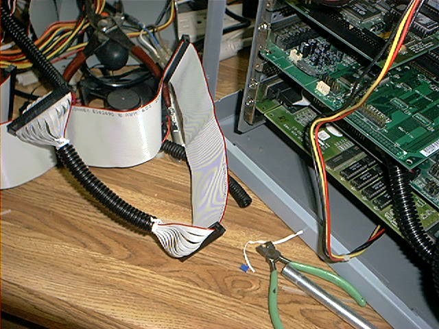 I bundled my cables using more of that split loom tubing. I put a zip tie around the bundle of strips at each end of to keep things in order. I show twisty ties in the pic- they were temporary until I could scrounge up more zip ties.
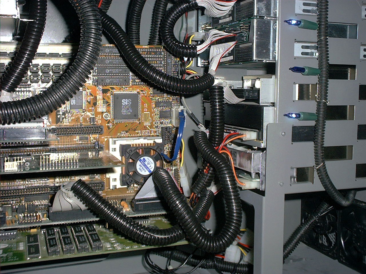 Some of the finished cables in place.
end product
Now comes the fun part- putting it all together and making it work.
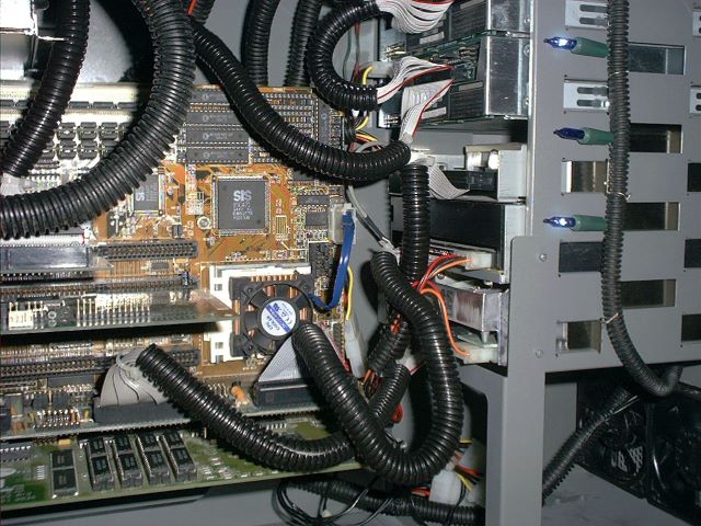 Inside
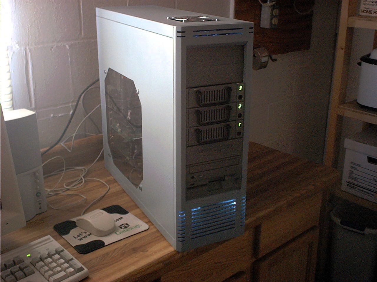 The front
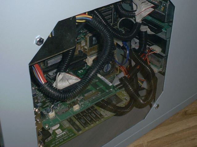 The window
 The access panel. Sorry the picture quality is poor. I tried to get some better shots, but the memory card in my camera died. :(
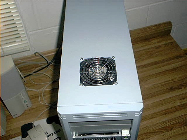 The top
 and one switch to run it all. That top "power supply" is just an empty carcass to block the gaping hole. Note the cable pass thrus cut in the back panel.
update 1
We played with the hardware configuration a few times. The first update was installing an AMD 5x86 133 into the original motherboard. It gave us an opportunity to snap a few slightly better quality pics.
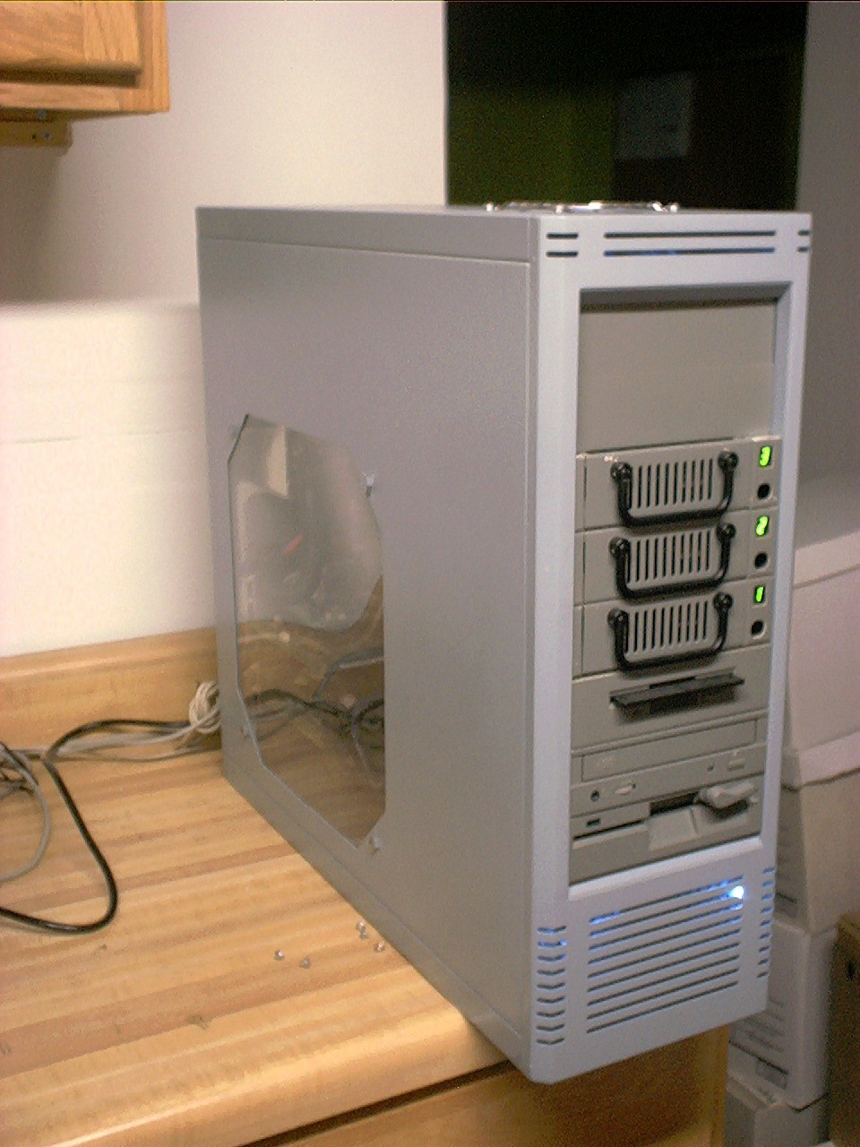 The front
 The logo panel in profile
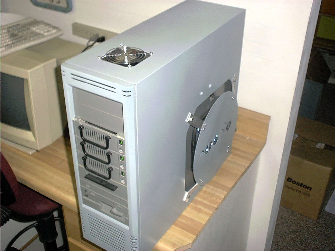 The top
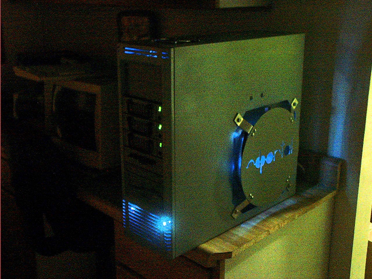 The case lit up.
update 2
The next update was installing better quality lighting- CCFL? LED? Nope. rope light. This is budget modding. I don't think any of these updates made it to a live website. If they did I don't have backups of the site and it was likely very short-lived. I also installed a new motherboard, CPU, video card, etc... Sadly I can't find the hardware specs documented- just a blurry pic of the video card. This was a complete refresh and rewire. I also cut a larger cable pass through on the rear of the case.
components
- motherboard, model unknown
- CPU, model unknown
- RAM, capacity and type unknown
- Video card, model unknown
- Accelerator - 3Dfx Orchid Righteous Voodoo 1
- ISA ESS 1868 sound card (probably, would have been from original build)
- NIC, model unknown
- ISA Future Domain 8bit SCSI controller card (probably, would have been from original build)
- Heatsink/cooler
- Serial headers
hardware
- Radio Shack cable tie mounts 10 pack x1
- Assorted zip-ties/ny-ties/zap-straps
- Blue rope light
- Assorted pieces of split loom
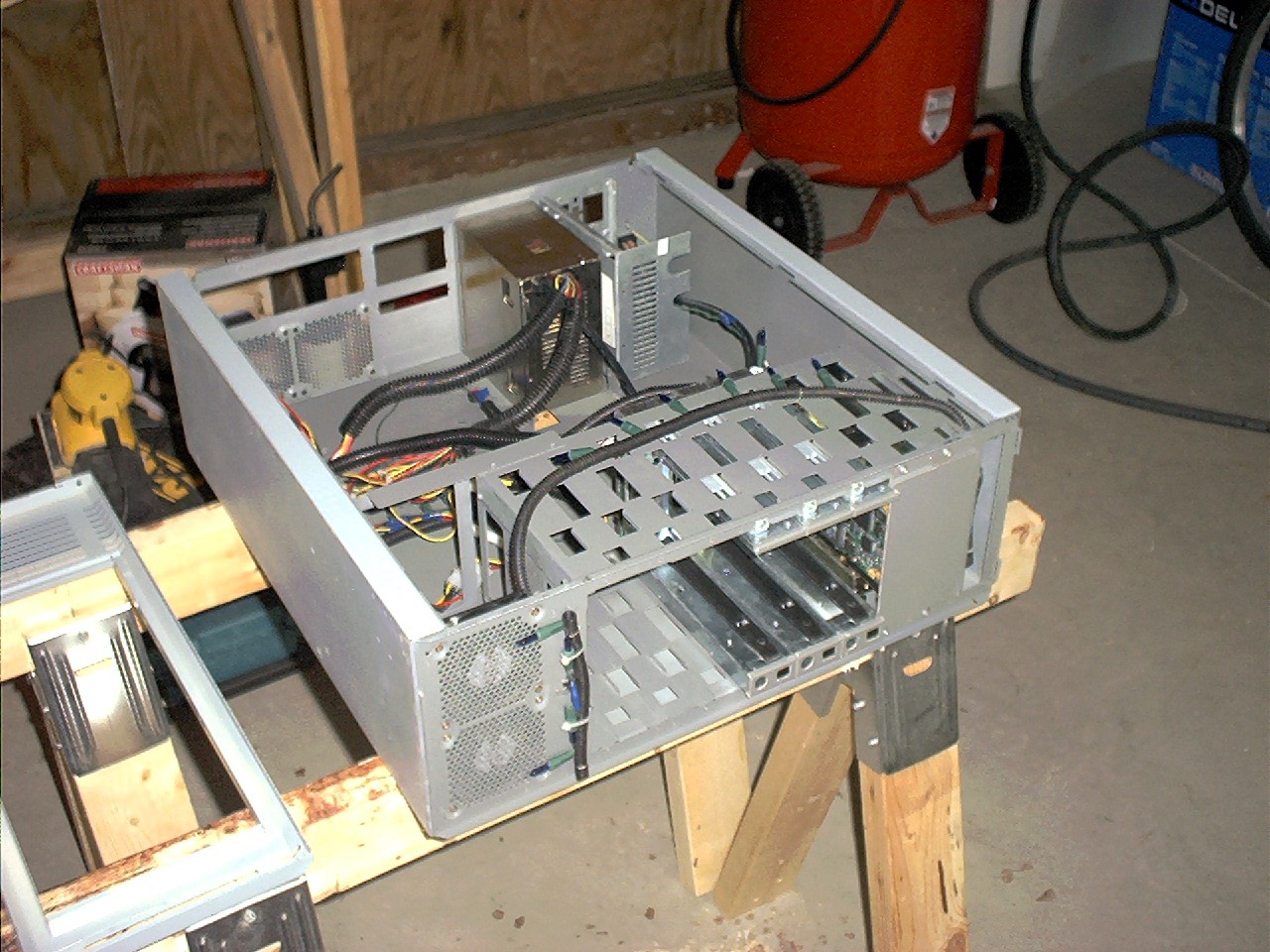 The first step was pulling the covers and removing the computer components and motherboard tray leaving the original wiring and lighting.
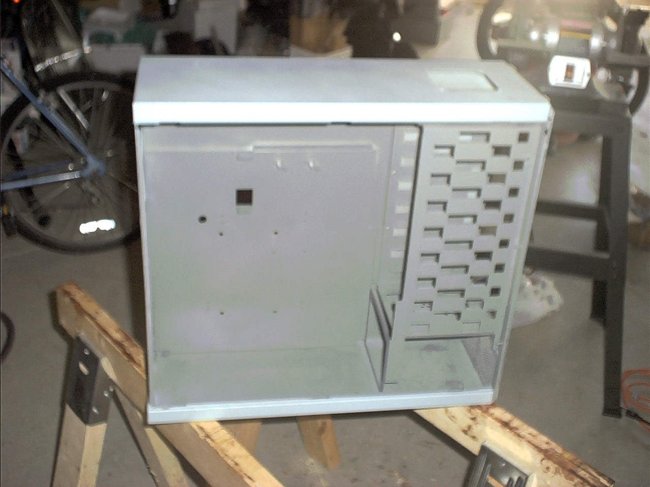 All the wiring and lighting stripped. Back to the bare case.
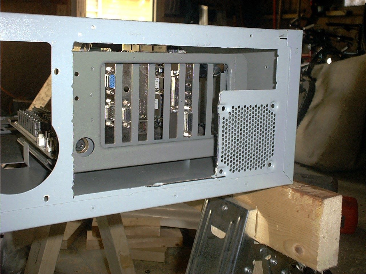 I cut away a large portion of the rear panel to facilitate cabling the new 3D accelerator.
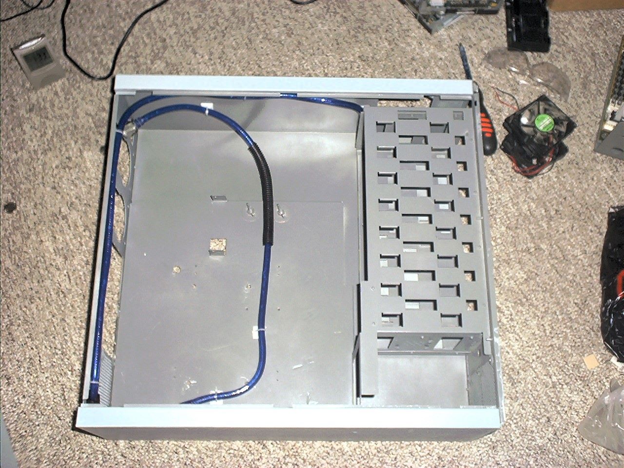 Routing rope light. I used sections of split loom to black out areas of the rope light. I mounted the rope light useing zip-ties and self-adhesive cable mounts. I somehow worked out to be the exact amount needed for the interior, logo panel and front bezel.
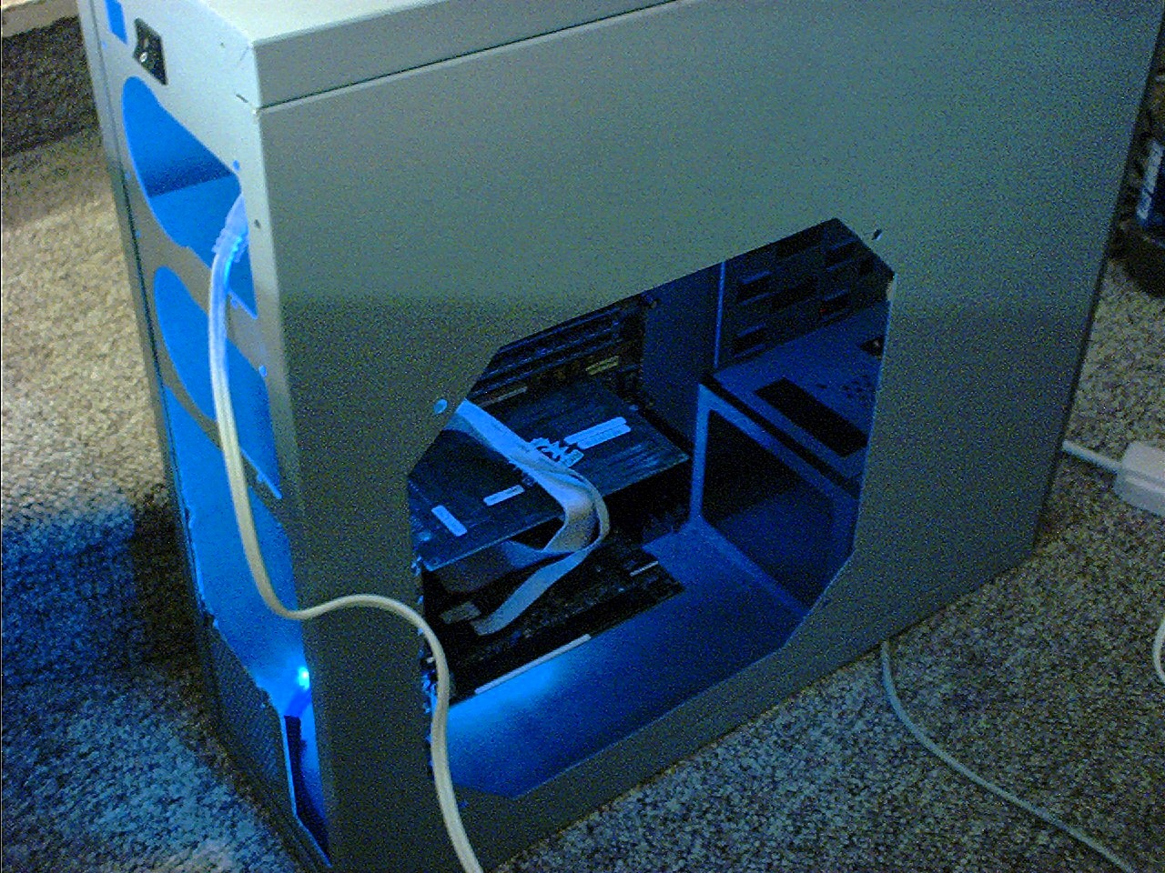 Test fitting the new components in the motherboard tray with the new lighting.
update 3
The final iteration of the elite. After re-working the lighting I went through the fan setup and scratch built a wiring harness to replace a bunch of janky splitters. I also found a new motherboard tray and yet another new motherboard. I updated the video card, replacing the old video card and VooDoo accelerator with an AGP card of some flavor. Last, I installed a fan in the window panel to improve CPU cooling. Again, I don't think any of this work made it to a live website and is undocumented.
components
- motherboard, model unknown, probably Super Socket 7, dual AT and ATX power headers, AGP, PCI and ISA support.
- CPU, model unknown
- RAM, capacity and type unknown
- Video card, AGP of some flavor
- Sound card, model unknown
- NIC, model unknown
- SCSI controller, 16 bit ISA, model unknown
- Heatsink/cooler, Thermaltake, model unknown
hardware
- Radio Shack blade connectors, male and female
- Heat shrink
- Assorted zip-ties/ny-ties/zap-straps
- Assorted pieces of split loom
- Lamp wire, clear jacket
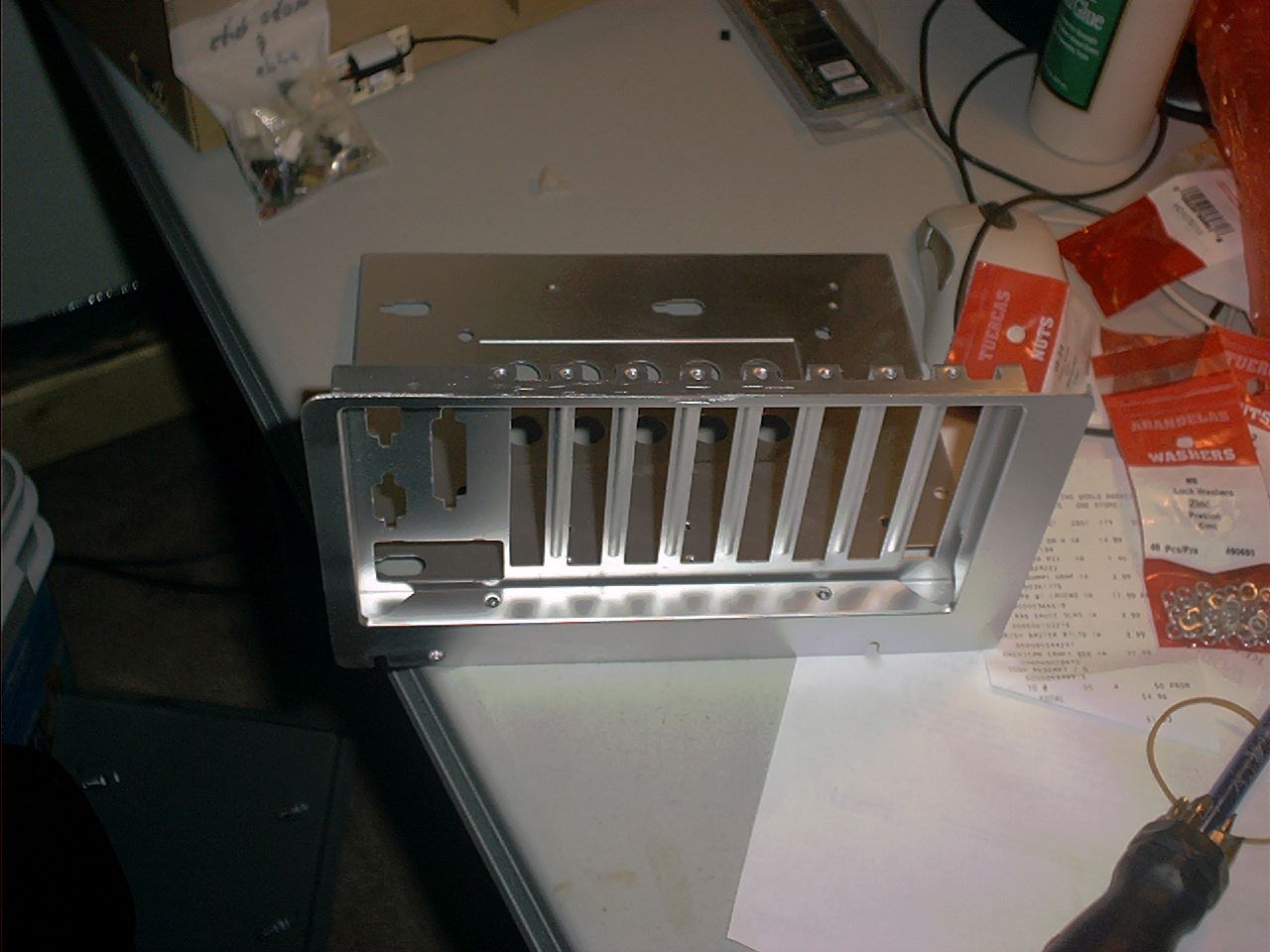 New motherboard tray.
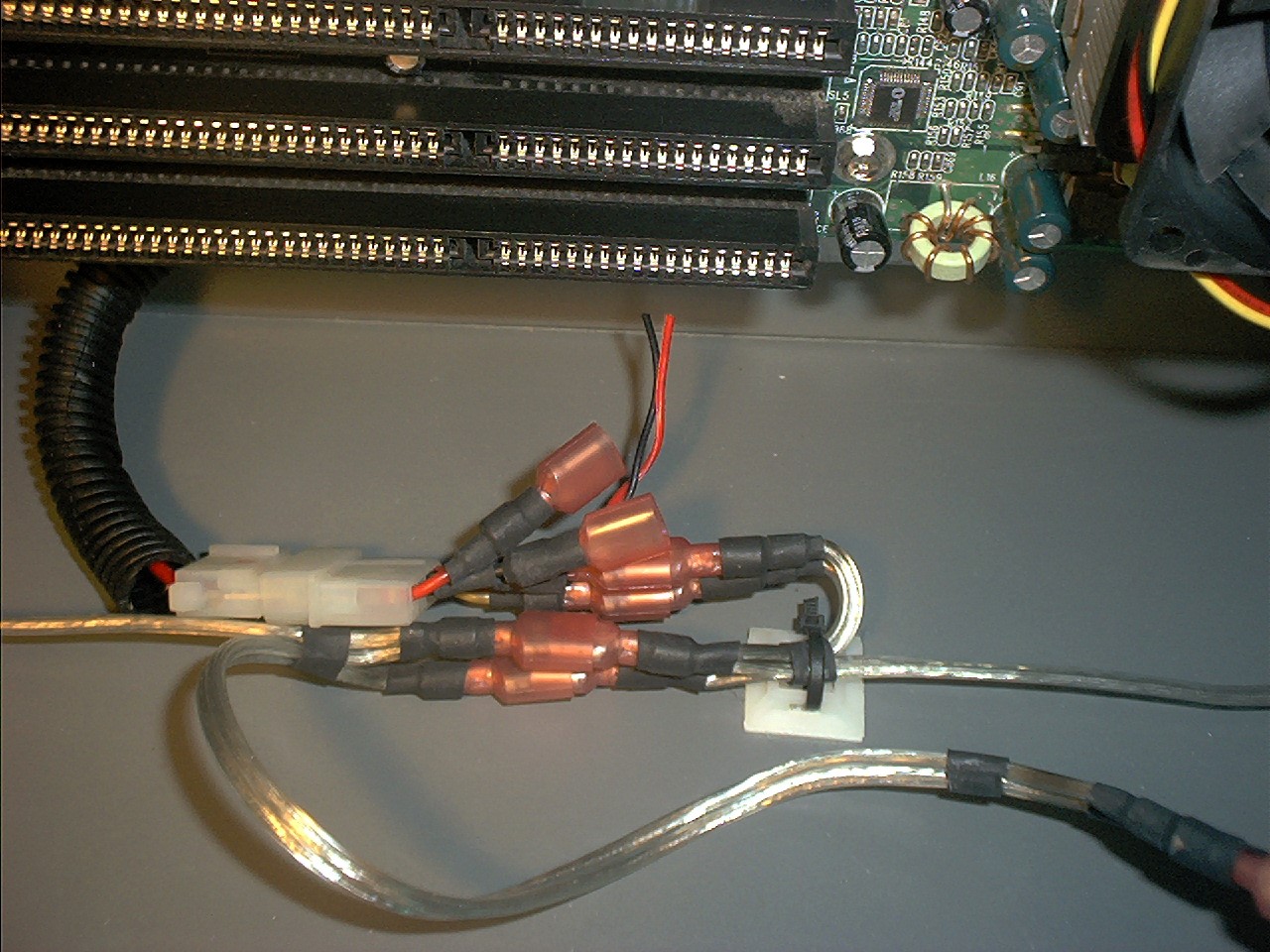 Detail shot of the new fan bus wiring.
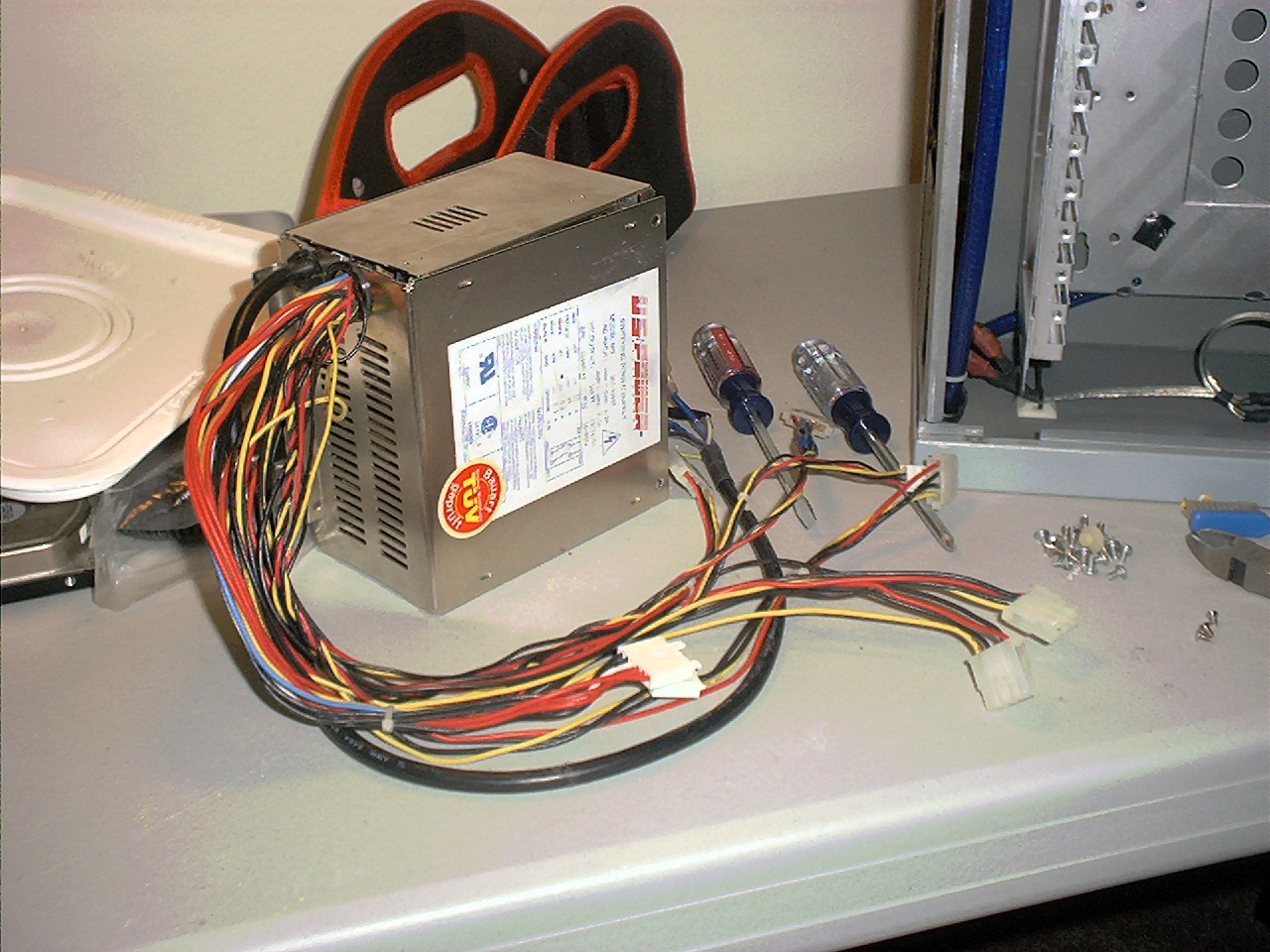 I removed the power supply cover and re-wrapped the wires, tucking the warp ends into the case for a cleaner appearance
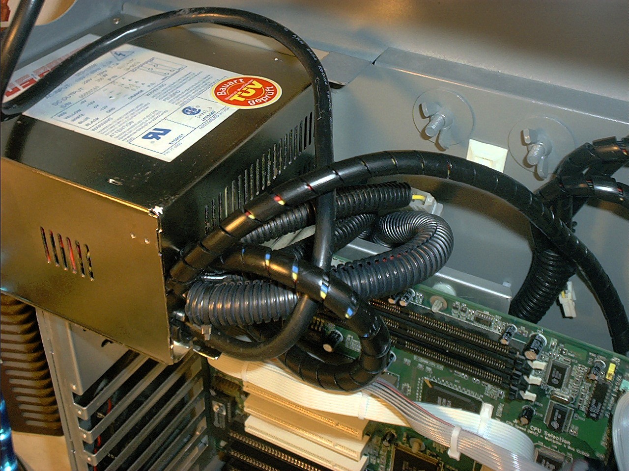 Closeup of the power supply cable wrapping.
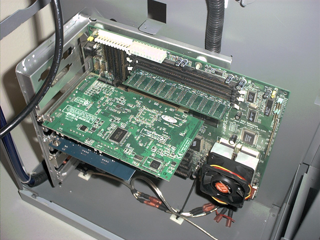 New motherboard and components installed in the tray and test fit in the case.
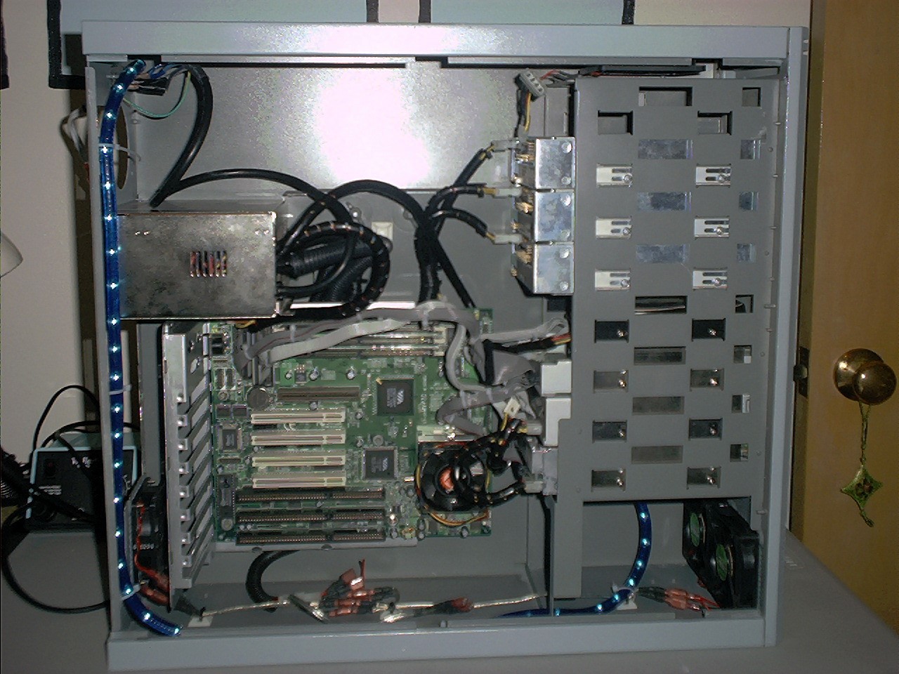 Installing data cables with the new motherboard, refreshed power supply, fan bus wiring, and lighting in place.
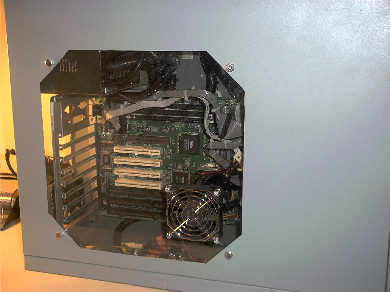 New fan installed over the CPU.
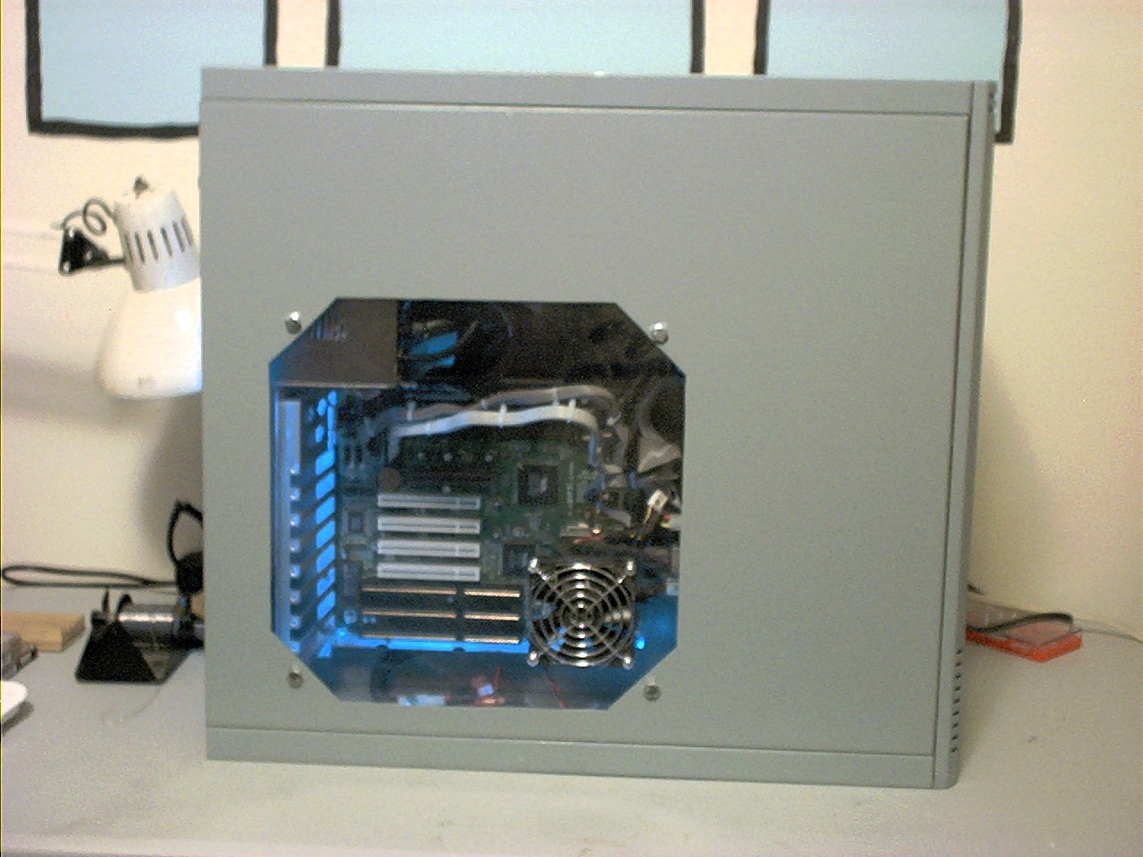 Final shots.
 .
.
 .
.